EUKYX-199-3100_G5S2_Instruction_Vol3_E.pdf - 第213页
EUKYX 2-65 199-3100 3.2 PCB T ransfer Mode • Set-u p 2 [1] [2] [3] [4] [5] [6] [7] [8] [9] [10] [11] F3B77A [ 1 ] Input mo de Select a parameter accord ing to the PCB un load in g system of the input m ach ine. Conv eyor…
EUKYX
2-64199-3100
3.2 PCB Transfer Mode
3.2 PCB Transfer Mode
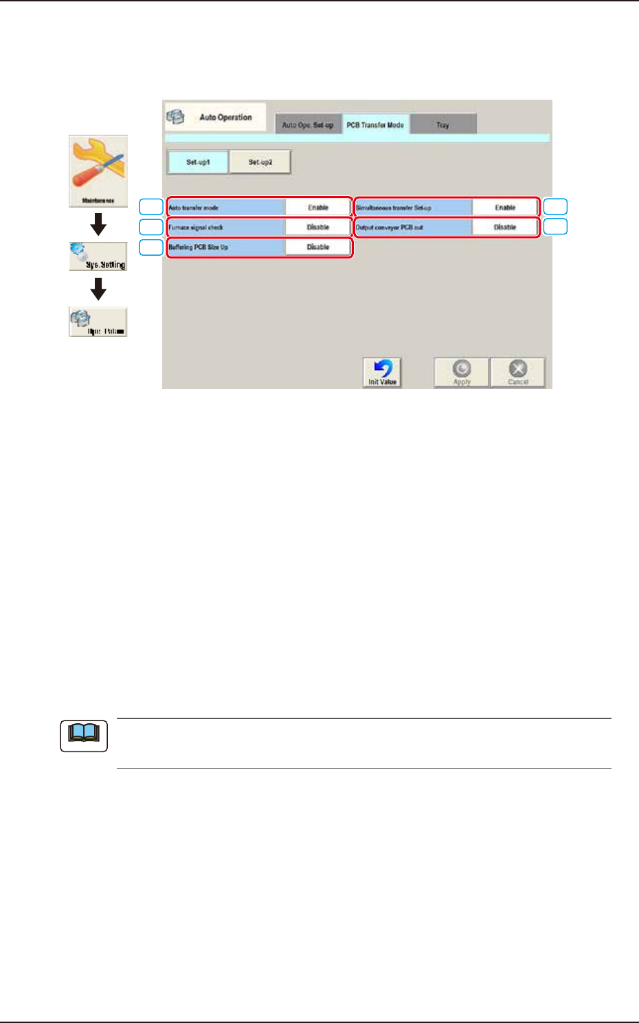
Pressing the [PCB Transfer Mode] tab on the "Auto Operation" window displays the following
window.
[4]
[5]
[1]
[2]
[3]
Graphic
Development
F3B76A
• Set-up 1
[1] Auto transfer mode
Whether or not the automatic transfer mode in the PCB discharge operation is used, is set in
this selection box.
Enable
The discharge of the PCB where the components have been placed, on the PCB positioning
unit, is performed at the same time of the transfer of the next PCB to the PCB positioning unit.
Disable
The discharge of the PCB (finished PCB) to the output machine is performed in this PCB
transfer mode, when the components have been placed on the PCB on the PCB positioning
unit and there is no PCB on the buffer section and the conveyor movement is not started.
[2] Furnace signal check
Set "Disable" or Enable" to determine whether or not the furnace signal check function should be
activated.
When "SMEMA" is set in the "Input mode" text box of the label "Input Setup" or in the "Output
mode" text box of the label "Output Setup", this function cannot be used.
[3] Buffering PCB Size Up
It is activated when “Enable“ is selected for “Simultaneous transfer Set-up“.
Select “Disable” or Enable” for buffering the PCB X size from 280 to 410 mm to the supply
conveyor.
[4] Simultaneous transfer Set-up
Select “Enable” or “Disable” to determine whether or not the PCB transfer should be made
simultaneously between the input and positioning conveyors and between the positioning and
output conveyors.
[5] Output conveyor PCB out
Set “Disable” or “Enable” to determine whether or not a disengaged PCB should be detected in the
output conveyor section.
Note
EUKYX
2-65199-3100
3.2 PCB Transfer Mode
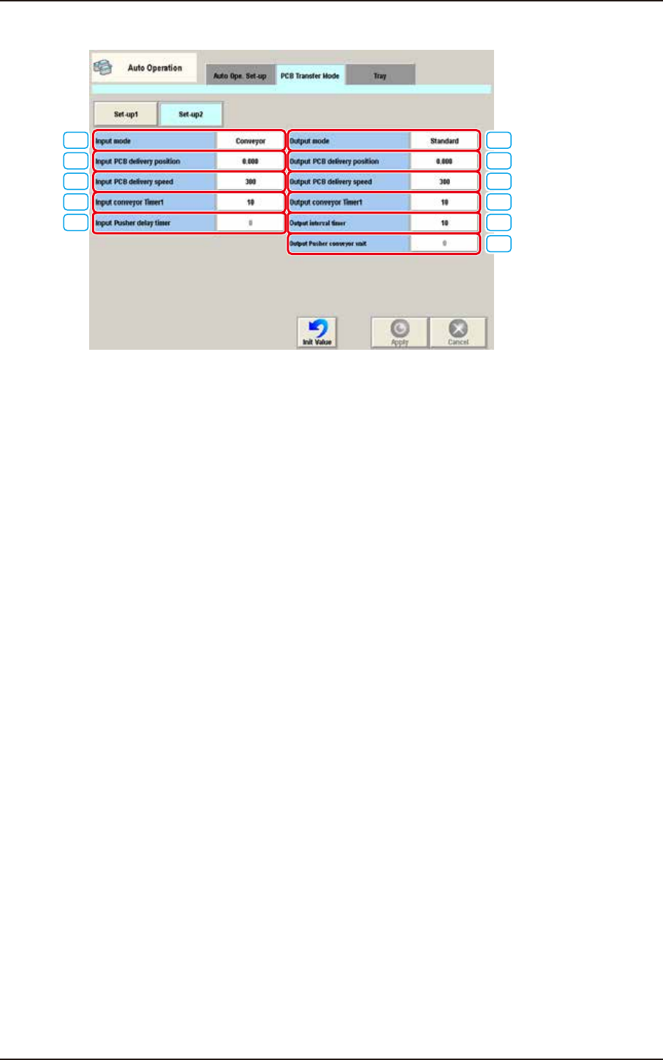
• Set-up 2
[1]
[2]
[3]
[4]
[5]
[6]
[7]
[8]
[9]
[10]
[11]
F3B77A
[1] Input mode
Select a parameter according to the PCB unloading system of the input machine.
Conveyor
The input machine is activated to receive a PCB from the input machine when the PCB
transfer signal is received from the input machine.
Pusher
The pusher of the input machine forces a PCB out to the input conveyor of the machine.
When the PCB detection sensor (for the pusher) is not provided at the inlet side of the input
conveyor, do not set "Pusher" in the text box.
SMEMA
PCBs are transferred according to the "SMEMA" standard.
Conveyor 2
PCB is delivered same as the pusher, however, the work request signal is turned off after
delivering PCB.
[2] Input PCB delivery position [mm]
Set the PCB delivery position.
[3] Input PCB delivery speed [mm/sec]
Set the PCB delivery speed.
Default
: 300 [mm/sec]
EUKYX
2-66199-3100
3.2 PCB Transfer Mode
[4] Input conveyor Timer1 [sec]
Set the time to limit the operating time (PCB reception from the input machine) of the input
conveyor. This timer measures the operating time of the input conveyor and is used to detect an
interrupted PCB.
Add 2 seconds (approx.) to the time required for PCB reception from the input machine and set
the time in the text box.
[5] Input Pusher delay timer [sec]
When "Pusher" is set in the "Input mode" text box of the label "Input Setup", it is required to specify
the delay (waiting) time for the loading action to start after the inlet sensor has detected a PCB.
[6] Output mode
The PCB delivery to the output machine is set in this section.
Standard
When the output machine is manufactured by us, set "Standard" in the text box.
When the work request signal is received from the output machine, the PCB transfer signal of the
machine is turned ON and a PCB is transferred to the output machine by the output conveyor.
When the work request signal is not turned OFF within the specified time after a PCB unloading
action has started, the machine stops in an error condition.
Interval
When the work request signal of the output machine is turned ON, PCBs on the machine side are
transferred to the output machine.
The conveyor stops when the output conveyor timer 1 has reached the specified time.
The machine starts its unloading actions when the unloading condition is fulfilled after the conveyor
has stopped running and the time specified in the "Output interval timer [sec]" text box has elapsed.
No error detection is made.
SMEMA
PCBs are transferred according to the "SMEMA" standard.
[7] Output PCB delivery position [mm]
Set the PCB delivery position.
[8] Output PCB delivery speed [mm/sec]
Set the PCB delivery speed.
• Default : 300 [mm/sec]
When the unloading system of the output machine is used in a mode other than the standard
one and the PCB transfer speed of the output machine is slow, the transfer speed must be
adjusted to one on the output machine side.
[9] Output conveyor Timer1 [sec]
Set the time to limit the operating time (PCB reception by the output machine) of the output conveyor.
Add 2 seconds (approx.) to the time required for PCB reception by the output machine and set
the time in the text box.
[10] Output interval timer [sec]
When “Interval” is set in the “Output mode” text box, set the time as interval time for PCB
unloading actions.
[11] Output Pusher conveyor wait [sec]
When “SMEMA” is set in the “[9] Output mode” text box, the output conveyor wait time is set in
this text box.
Note
Note
Note
Note