EUKYX-199-3100_G5S2_Instruction_Vol3_E.pdf - 第88页
EUKYX 1-39 199-3100 5.8 PCB Recog/Beam • Glass jig boar d JG -0 1 66 (PEC Recognit ion Calibration Jig) For the "PEC Recogn ition Camera & Bea m Of fs et" teachi ng , the fol lowi ng gl ass jig board i s us…
EUKYX
1-38199-3100
5.8 PCB Recog/Beam
5.8 PCB Recog/Beam
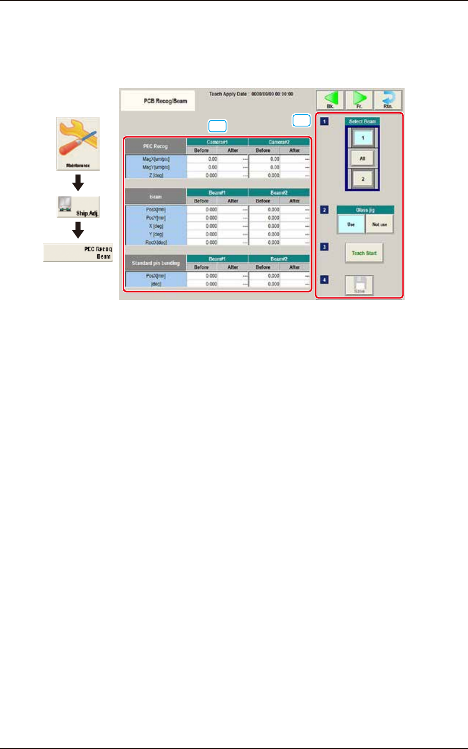
The corresponding window performs the teaching operation for the PEC recognition camera offset
(Magnification X(Horizontal), Y(Vertical) and Z(Angle), Beam offset (Beam X(Horizontal), Beam
Y(Vertical), Beam Angle X and Y).
[1]
[2]
Graphic
Development
F3A35
[1] Teaching Data Display Section
Displayed are the offset data items for the designated beam.
[2] Teaching procedures section
The following buttons are arranged in teaching procedures section.
Select Beam
Selects the PEC recognition camera/beam to be taught.
Glass Jig
[Use] button
When this button is pressed to use the glass jig board, the color of the button turns light
blue.
[Not use] button
When this button is pressed not to use the glass jig board, the color of the button turns light
blue.
[Teach Start] button
When pressed, this button executes the teaching operation.
[Save] button
When this button is pressed, the teaching results are saved.

EUKYX
1-39199-3100
5.8 PCB Recog/Beam
• Glass jig board JG-0166 (PEC Recognition Calibration Jig)
For the "PEC Recognition Camera & Beam Offset" teaching, the following glass jig board is used.
Before the teaching operation, position and clamp the glass jig board on the PCB positioning center.
• Teaching Procedure
(1) Select the Beam (1 or 2) for which the teaching is performed.
(2) Press the [Use] button in the "Glass Jig" section.
(3) Press the [Teach Start] button. The designated beam (1 or 2) will move to the specified
recognition mark position and the following teaching operation will be performed.
• PEC Recognition Camera Magnification X (Horizontal), Y (Vertical), Z (Angle) Teaching
(Camera 1 or 2)
• Beam X (Horizontal) and Y (Vertical) Offset Teaching (Beam 1 or 2)
• Beam Angle Z, Angle Y, Rectangular X Offset Teaching (Beam 1 or 2)
• Pilot Pin Bending Position X Side, Angle (Beams 1 and 2)
• When any recognition error occurs during the teaching or the [STOP] button is pressed
on the operation panel, the machine is stopped temporarily. In this case, re-start is available.
• During this temporary stop mode, the selection of any other menu item is unavailable.
When the teaching is completed, the designated head returns to the home position
automatically. The teaching results and mark recognition results during the teaching (XY
Angles) are displayed in the display area on the "PEC Recognition Camera & Beam
Offset" window.
(4) Press the [Save] button to save the teaching results.
Procedure
Note
EUKYX
1-40199-3100
5.9 Cmp Recog Pos
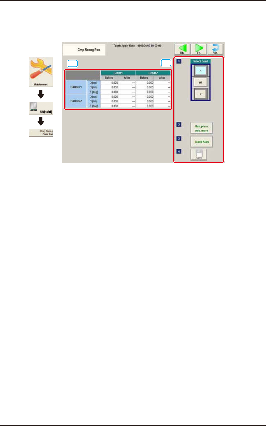
5.9 Cmp Recog Pos
This window performs a teaching operation on the component recognition camera offsets (X (mm)
Horizontal, Y (mm) Vertical, and Z (deg) Angle).
[1]
[2]
Graphic
Development
F3A36
[1] Teaching Data Display Section
Displayed are the each offset data items for the designated camera and head.
[2] Teaching procedures section
The following buttons are arranged in teaching procedures section.
Select head
Selects the head whose component recognition camera is taught.
[Noz. Place. Pos. move] Button
The head is moved to the position where the nozzle to be used for the teaching can be
attached easily.
[Teach Start] button
Starts the teaching.
[Save] button
The teaching results are saved.