EUKYX-199-3100_G5S2_Instruction_Vol3_E.pdf - 第198页
EUKYX 2-50 199-3100 2.9 Comp. Recog [2] Z (Angl e) [Ang] Set the parameters repre sentin g the angu la r devi ati ons in the scan ni ng coordin ates of the component recognit ion cameras based on the machi ne reference X…
EUKYX
2-49199-3100
2.9 Comp. Recog
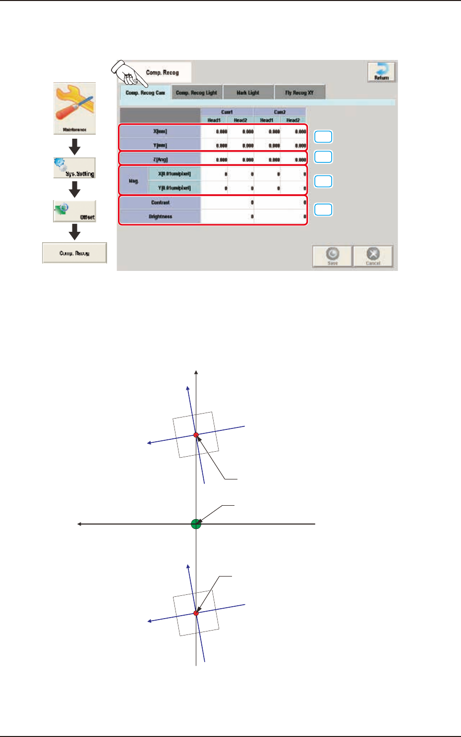
2.9.1 Comp. Recog Cam
Pressing the [Comp. Recog Cam] tab on the "Comp. Recog" window displays the following window.
[1]
[2]
[3]
[4]
Graphic
Development
F3B62
[1] X (Horizontal) / Y (Vertical) [mm]
The set parameters are used to adjust the positional deviations based on the design dimensions
between the machine reference coordinate origin and the center of the component recognition
cameras.
Xm(+)
Ym (+)
Xc(+)
Yc(+)
Xc(+)
Yc(+)
Center of Component
Recognition Camera
Center of Component
Recognition Camera
Pm. Machine Reference
Coordinate Origin
Xm-Ym
Xc-Yc
: Machine Reference
Coordinate System
: Component Recognition
Camera Coordinate System
F3B63
EUKYX
2-50199-3100
2.9 Comp. Recog
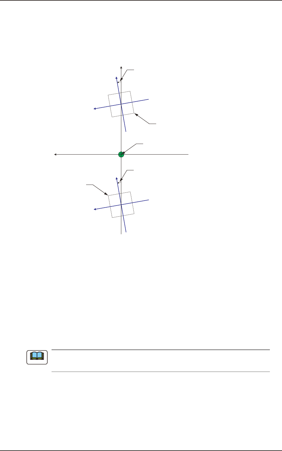
[2] Z (Angle) [Ang]
Set the parameters representing the angular deviations in the scanning coordinates of the
component recognition cameras based on the machine reference X/Y coordinates (Xm-Ym).
When the camera scanning coordinates are shifted counterclockwise to the machine reference X/Y
coordinate system, a plus sign must be affixed to each offset data.
Xm(+)
Ym(+)
Xc(+)
Yc(+)
Xc(+)
Yc(+)
Angle of Component Recognition
Camera
Angle of Component Recognition
Camera
Component Recognition
Camera
Component Recognition
Camera
Pm. Machine Reference
Coordinate Origin
Xm-Ym
Xc-Yc
: Machine Reference
Coordinate System
: Component Recognition
Camera Coordinate System
F3B64
[3] Mag. X (Horizontal) and Y (Vertical) [0.01 µm/pixel]
Set how many micrometers should be equivalent to one pixel to specify the magnification of the
component recognition camera.
This offset value is calculated automatically by means of the teaching operation using the
magnification measuring jig.
• Default : 6060
[4] Contrast and Brightness
The brightness of the image captured by the component recognition camera can be adjusted.
• Default
Contrast: 102 / Brightness: 128
(a) The larger the value for “Contrast” is, the stronger the chromaticness becomes.
(b) The larger the value for “Brightness” is, the brighter the whole view becomes.
Note
EUKYX
2-51199-3100
2.9 Comp. Recog
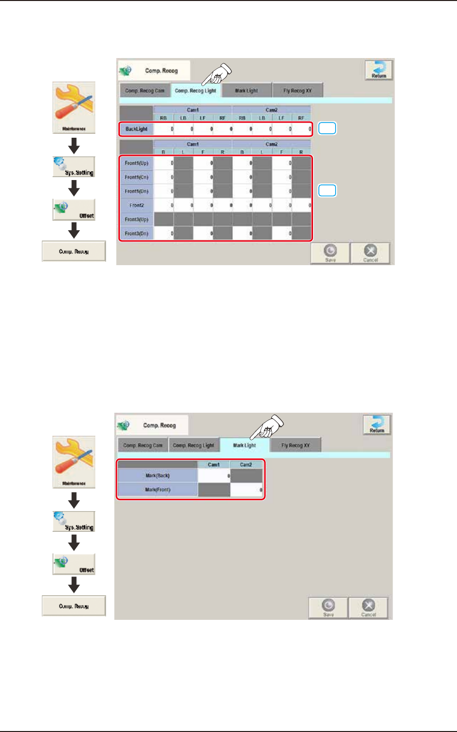
2.9.2 Comp. Recog Light
Pressing the [Comp. Recog Light] tab on the "Comp. Recog" window displays the following window.
[1]
[2]
Graphic
Development
F3B65
[1] Back Light
Set the light level for Comp. Recog Light.
[2] Front 1 (Up) / (Cn) / (Dn) / Front 2 / Front 3 (Up) / Front 3 (Dn)
Set the light level for Comp. Recog Light.
2.9.3 Mark Light
Pressing the [Mark Light] tab on the “Comp. Recog” window displays the following window.
Graphic
Development
F3B66
Mark (Back) / Mark (Front)
Cam1 / Cam2
The brightness level for the reference mark lighting is set in these text boxes.