EUKYX-199-3100_G5S2_Instruction_Vol3_E.pdf - 第53页
EUKYX 1-4 199-3100 3. Unit Change 3 . Uni t Change Thi s wi ndow enab les the operator to perform the unit c han ge i n the system. [1] [2] [3] [3] [2] [4] [4] [5] [5] [6] [7] Graphic Development F3A5A [ 1 ] Unit Imag e …
EUKYX
1-3199-3100
2. MAINTENANCE
2. MAINTENANCE
This window enables you to adjust the machine, check the performance, and perform various
teaching operations. When the [Maint.] button in the "TOP" page is pressed and the logging-in
operation is performed, the "Maintenance" window appears.
The indication on the window varies depending on the user's access authorization .
Graphic
Development
F3A3
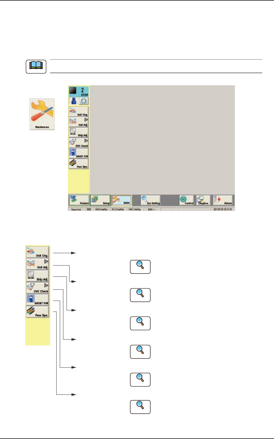
The [Maintenance] main menu buttons are arranged to display the operation windows where each
function in the Machine Maintenance (SPECIAL SEL) is executed.
[Unit Chg.]
Button
Open the "Unit Change" window.
Open the "Unit Adj." submenu.
Open the "Shipment Adj." window.
Open the "DVC Check" submenu.
[Unit Adj.]
Button
[Ship.Adj.]
Button
[DVC Check]
Button
:
:
:
:
Reference
Reference
Reference
Reference
Open the "MAINTWM" window.[MAINT WN]
Button
:
Reference
Open the "Pass Opn." window.[Pass Opn.]
Button
:
Reference
Refer to "3. Unit Change" in Chapter 1
for details.
Refer to "4. Unit Adj." in Chapter 1 for details.
Refer to "5. Shipment Adj." in Chapter 1
for details.
Refer to "6. DVC Check" in Chapter 1
for details.
Refer to "7. MAINTWM" in Chapter 1 for
details.
Refer to "8. Pass Operation (for Emergency)."
in Chapter 1 for details.
F3A4
Note
EUKYX
1-4199-3100
3. Unit Change
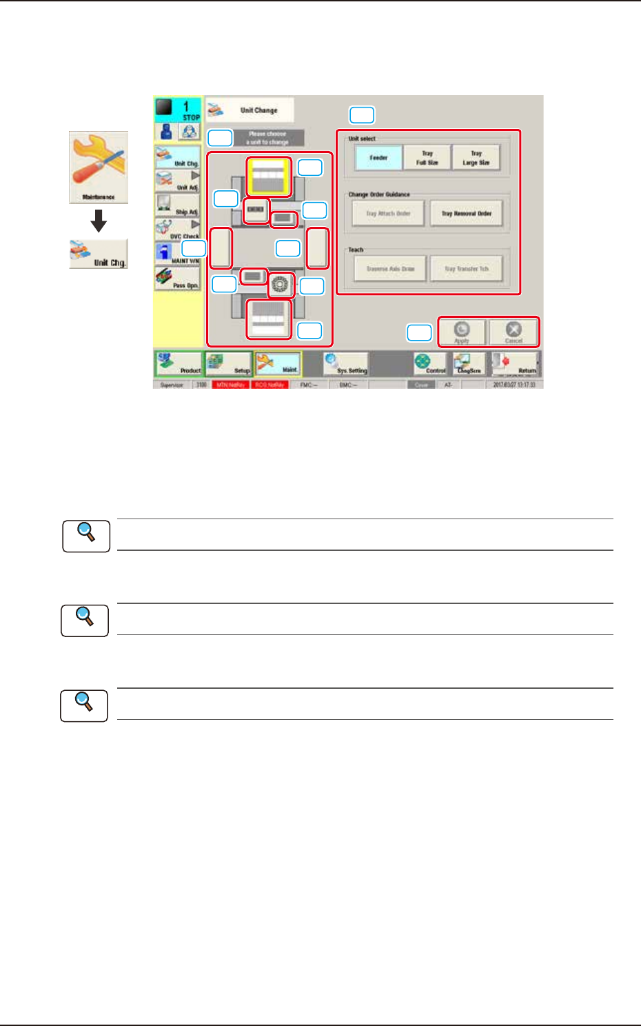
3. Unit Change
This window enables the operator to perform the unit change in the system.
[1]
[2]
[3]
[3]
[2]
[4]
[4]
[5][5]
[6]
[7]
Graphic
Development
F3A5A
[1] Unit Image Button
Shown are the image buttons for each unit and when the button for the unit to be changed is
pressed, the "Unit Operation Button" is changed.
[2] Head Unit Button
Refer to “3.1 Head Unit” in this chapter for the details.
[3] Nozzle Stocker Button
Refer to “3.2 Nozzle Stocker” in this chapter for the details.
[4] Feeder Unit Button
Refer to “3.3 Feeder Unit” in this chapter for the details.
[5] Conveyor Button
This button is optional.
[6] Unit Operation Button
The operation button for the unit selected using the unit image button, is displayed. The indication
is changed depending on the selected unit.
[7] [Apply] Button and [Cancel] Button
[Apply] Button : When pressed, this button applies the changed unit to the production line
configuration.
[Cancel] Button : When pressed, this button cancels the changed unit and returns it to the unit
before change.
Reference
Reference
Reference
EUKYX
1-5199-3100
3.1 Head Unit
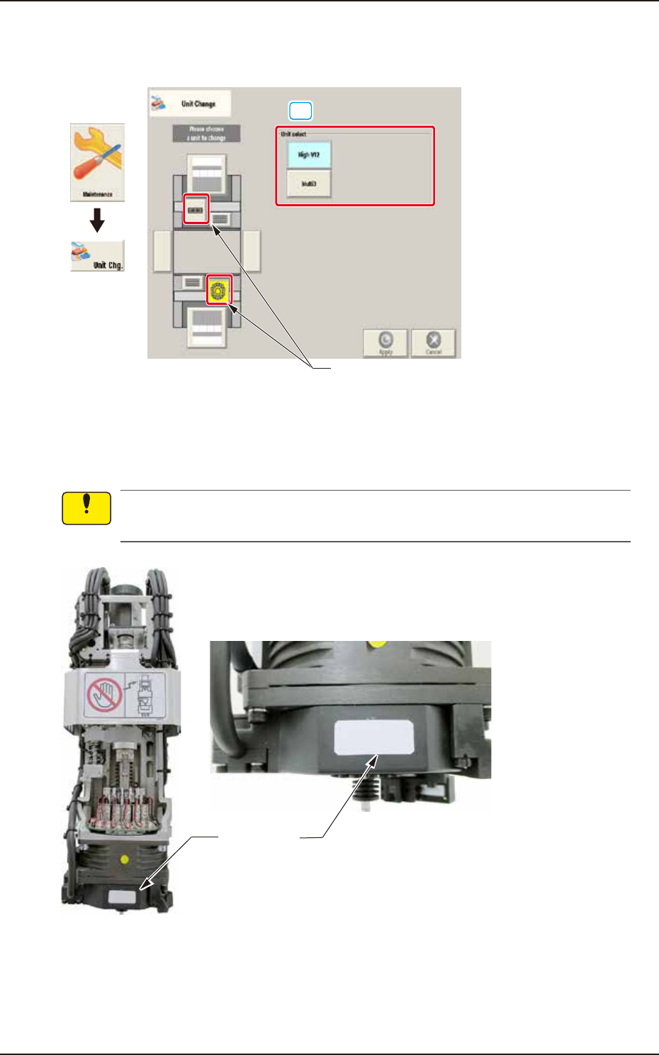
3.1 Head Unit
When the head unit button is pressed, the following window appears.
[1]
Head unit button
Graphic
Development
F3A6A
[1] Unit select
[High V12] Button : When pressed, the high-speed head is selected.
[Multi3] Button : When pressed, the multi-functional head is selected.
A white label is adhered to V12 head front. Make sure not to mount V10 head without label
when replacing head unit.
White label
Enlarged photo of head front
F3A6B
Notice