EUKYX-199-3100_G5S2_Instruction_Vol3_E.pdf - 第163页
EUKYX 2-15 199-3100 2.1 Device Offset 2. 1 . 1 7 S ide View Camera Pressi ng the [Side View Camera] tab on the "Device Of fset " window d ispla ys the fol low in g wi ndow . Graphic Development F3B90A 2. 1 . 1 …
EUKYX
2-14199-3100
2.1 Device Offset
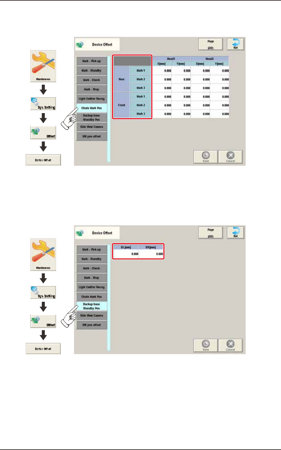
2.1.15 Chute Mark Pos
Pressing the [Chute Mark Pos] tab on the "Device Offset" window displays the following window.
Graphic
Development
F3B20A
2.1.16 Backup Base Standby Pos
Pressing the [Backup Base Standby Pos] tab on the "Device Offset" window displays the following
window.
Graphic
Development
F3B21A
EUKYX
2-15199-3100
2.1 Device Offset
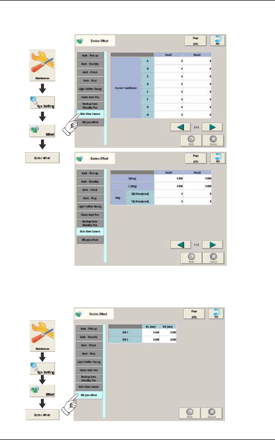
2.1.17 Side View Camera
Pressing the [Side View Camera] tab on the "Device Offset" window displays the following window.
Graphic
Development
F3B90A
2.1.18 Slit Pos Offset
Pressing the [Slit Pos Offset] tab on the "Device Offset" window displays the following window.
Graphic
Development
F3B91A
EUKYX
2-16199-3100
2.2 Feeder Base
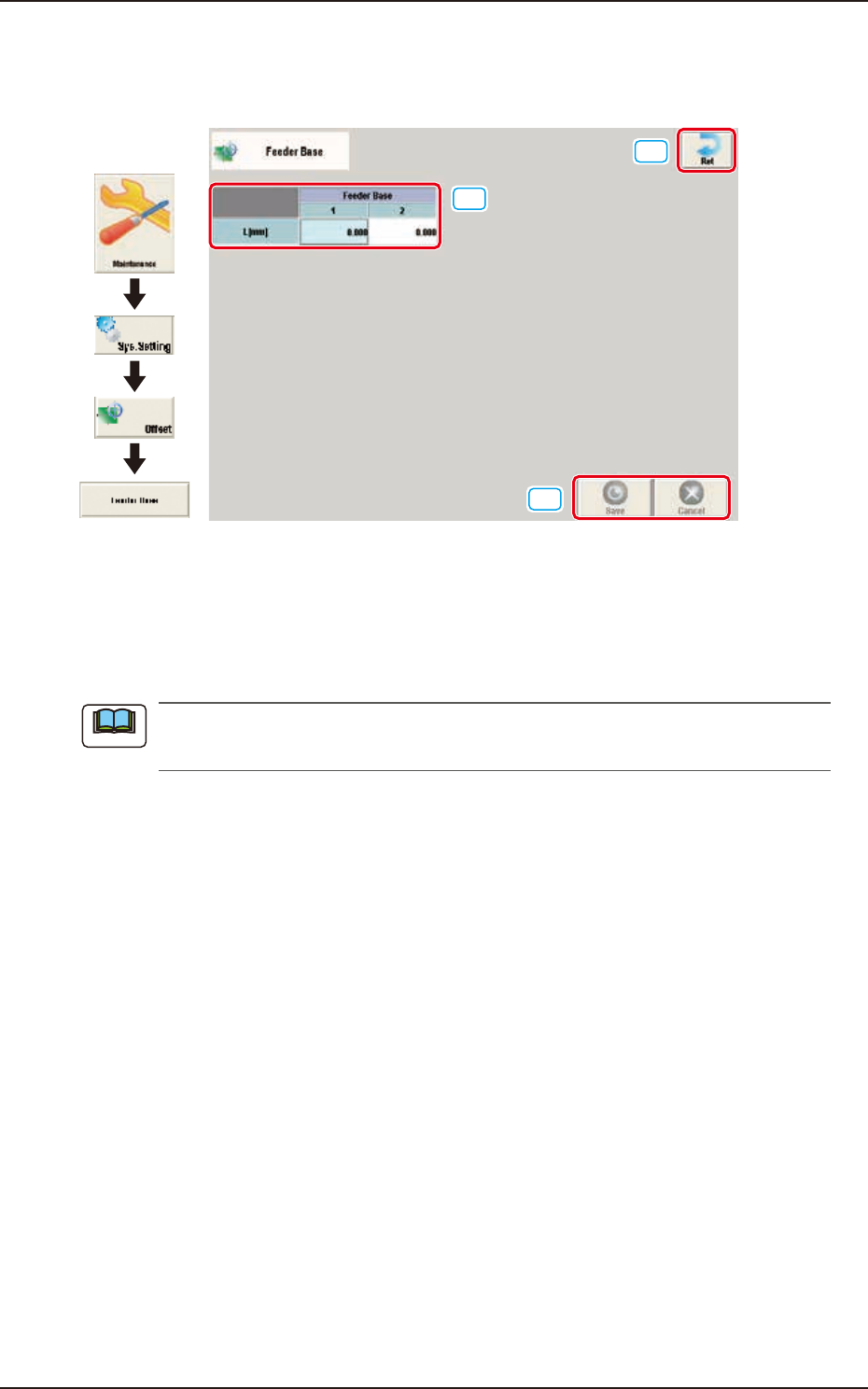
2.2 Feeder Base
Pressing the [Feeder base] button on the "Offset Data" window displays the following window.
[1]
[2]
[3]
Graphic
Development
F3B22
[1] L [mm]
The set offset parameters are used to adjust the positional deviations (height direction) based on the
design dimensions of Feeder Bases #1 and #2. When the feeder bases are installed lower than the
design values, a plus value must be entered in each text box.
The tilts of the PCB positioning sections on the feeder base sections are calculated on the X
and Y values of "Mark (Left)" and "Mark (Right)".
[2] [Ret] button
When this button is pressed, the window returns to the "Offset Data" window.
[3] [Save] button
When this button is pressed, the input data is applied.
[Cancel] button
When this button is pressed, the input data is cancelled and window returns to the save data.
Note