EUKYX-199-3100_G5S2_Instruction_Vol3_E.pdf - 第153页
EUKYX 2-5 199-3100 2.1 Device Offset 2. 1 .3 Pos Lev el Pressi ng the [Pos Leve l] tab on the " Devic e Of fs et" window di spla ys the fol lowi ng window . Graphic Development F3B6A BL [mm ] / BR [mm ] These p…
EUKYX
2-4199-3100
2.1 Device Offset
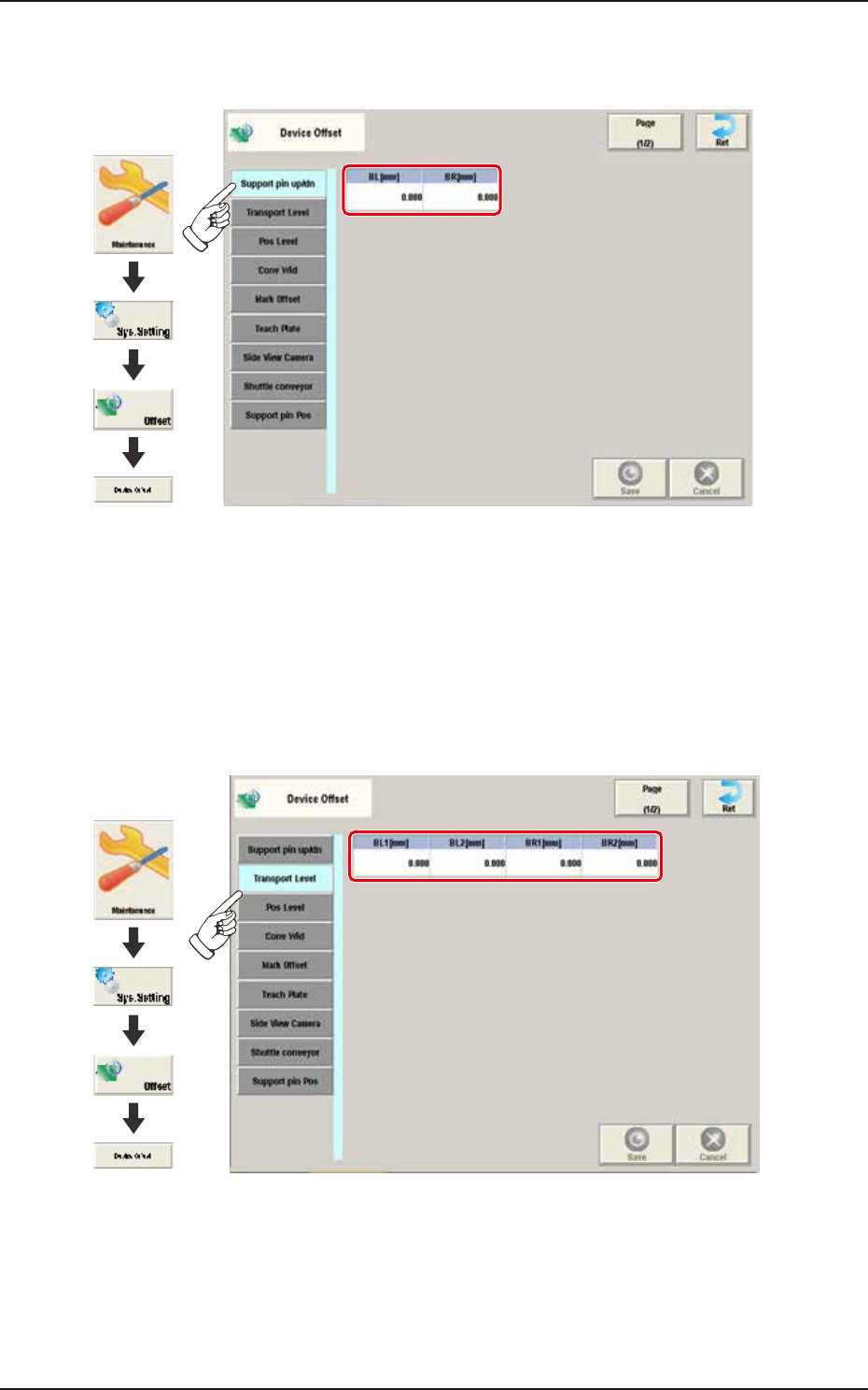
2.1.1 Support pin up/dn
Pressing the [Support pin up/dn] tab on the "Device Offset" window displays the following window.
Graphic
Development
F3B4A-1
BL [mm] / BR [mm]
This is the offset data for the origin position of the support pin up/down axis which ascends or
descends during PCB positioning.
A plus (+) value decreases the ascending stroke during PCB positioning.
2.1.2 Transport Level
Pressing the [Transport Level] tab on the “Device Offset” window displays the following window.
Graphic
Development
F3B5A
BL1 [mm] / BL2 [mm] / BR1 [mm] / BR2 [mm]
Each parameters are used to correct the positional deviations in PCB transfer positioning in
comparison with Support pin up/down operation.
EUKYX
2-5199-3100
2.1 Device Offset
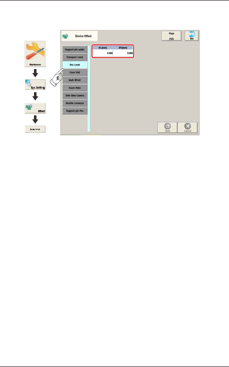
2.1.3 Pos Level
Pressing the [Pos Level] tab on the "Device Offset" window displays the following window.
Graphic
Development
F3B6A
BL [mm] / BR [mm]
These parameters are used to absorb the deviation in the PCB positioning level for the Support pin
up/down operation.
EUKYX
2-6199-3100
2.1 Device Offset
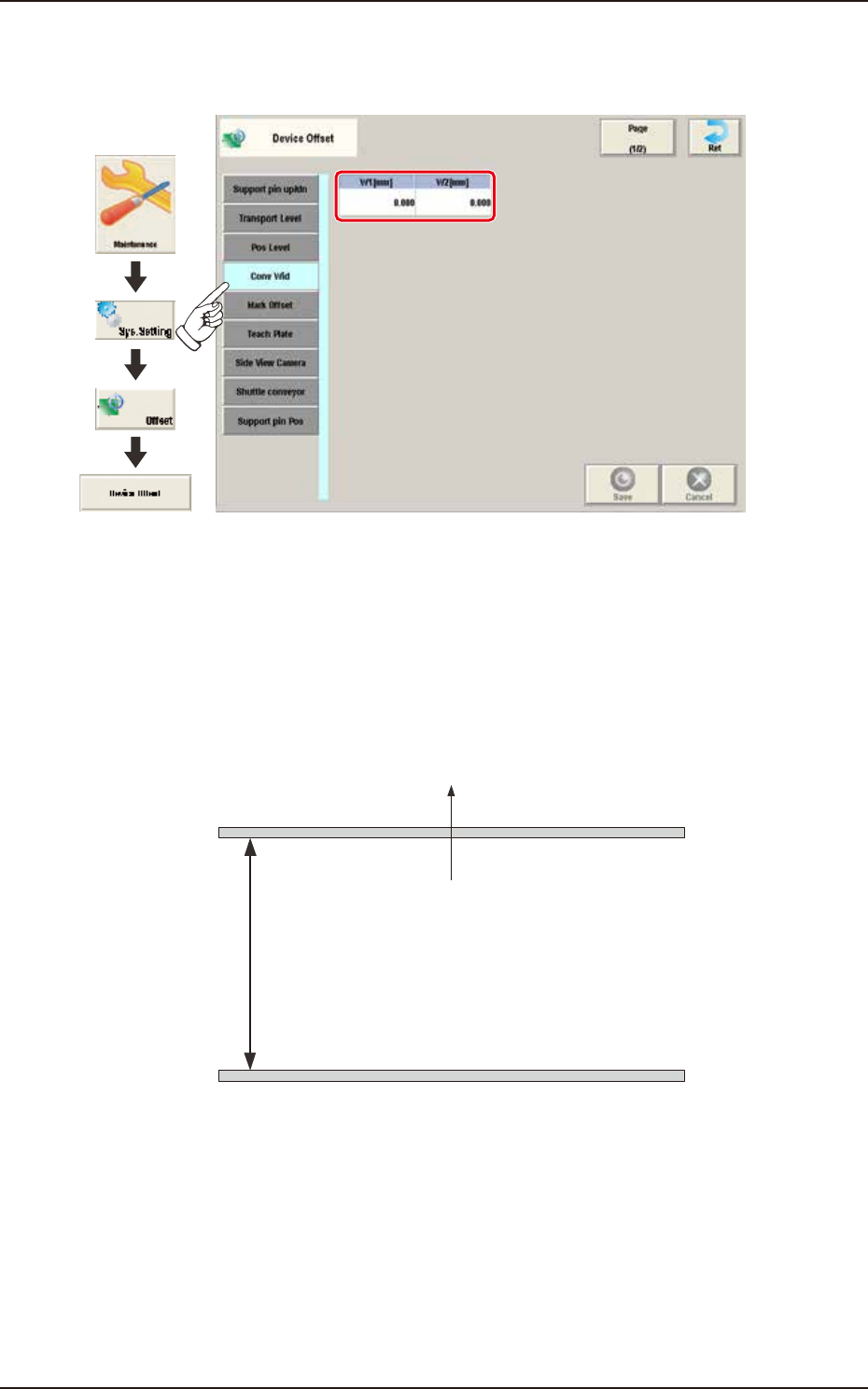
2.1.4 Conv Wid
Pressing the [Conv Wid] tab on the "Device Offset" window displays the following window.
Graphic
Development
F3B7A
W1 [mm] / W2 [mm]
This offset data is used to adjust the conveyor width to the absolute values. Enter the difference
between the actually measured value from the fixed chute to the movable chute and the half of the
specified width, when the conveyor width is set up to the specified one.
W1 Offset : In the case that the actually measured value is larger than half of the specified
one, a positive (+) value must be entered.
W2 Offset : It is not currently used.
Specified width
W1
(+)
(-)
Front Side of Machine
Movable Chute
Fixed Chute
F3B8