EUKYX-199-3100_G5S2_Instruction_Vol3_E.pdf - 第167页
EUKYX 2-19 199-3100 2.4 Beam 2 .4 Be am Pressi ng the [Beam ] but ton on the "Of fs et Data " win dow di spl ays the fol lowi ng wi nd ow . [1] [2] [3] [6] [7] [4] [5] Graphic Development F3B26 [ 1 ] X (Horizon…
EUKYX
2-18199-3100
2.3 Feeder A / Feeder B
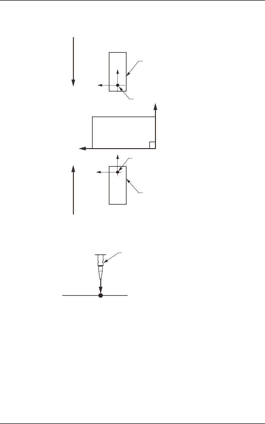
[2] X (Horizontal) and Y (Vertical) [mm]
These offset parameters are used to adjust the positional deviation based on the design dimensions
representing the component pickup position for each individual feeder slot Nos. (Fdr Nos.).
F211
F111
Rear Feeder
Front Feeder
Front Side of Machine
Y(+)
X(+)
Pickup Position
Pickup Position
Direction of Tape Feed
Direction of Tape Feed
F3B24
[3] L (Height) [mm]
Pickup Reference Level
Nozzle
L(+)
F3B25
When a value is entered with a plus (+) sign, the pickup height is reflected on the direction in
which the descending stroke of the nozzle will increase.
[4] [Ret] button
When this button is pressed, the “Offset Data” window is returned.
[5] Head Sel
Selects the head that calculates the feeder offset data automatically.
[6] (L) Data Calc Set (Blk)
The auto calculation methods of L data (teaching result offset value of pickup level) include “2Pt”
and “3Pt“. Pressing the [2Pt] or [3Pt] button calculates the L data of head 1 or head 2 on selected
block. The block is selected by changing the feeder with [1] Feeder Change tab.
[7] [Save] button
When this button is pressed, the input data is applied.
[Cancel] button
When this button is pressed, the input data is cancelled and window returns to the save data.
EUKYX
2-19199-3100
2.4 Beam
2.4 Beam
Pressing the [Beam] button on the "Offset Data" window displays the following window.
[1]
[2]
[3]
[6]
[7]
[4]
[5]
Graphic
Development
F3B26
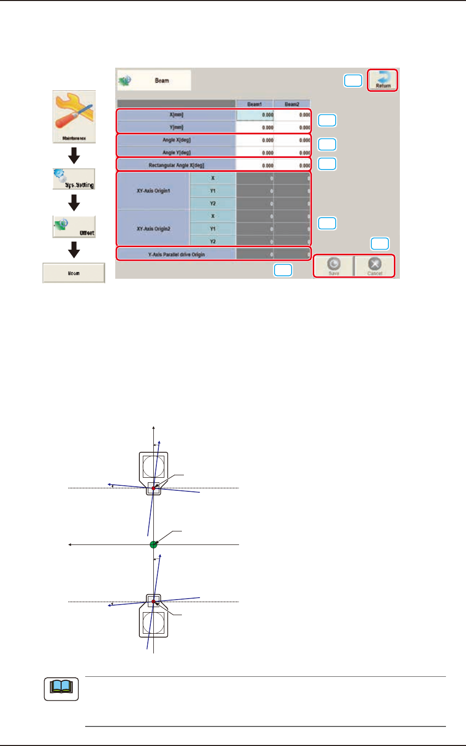
[1] X (Horizontal) and Y (Vertical) [mm]
The set parameters are used to adjust the positional deviation based on the design dimensions
representing the distance between machine reference coordinate origin and center of the PEC
recognition camera at head origin.
[2] Angle X and Angle Y [deg]
The set parameters are used to adjust the beam X and Y axes to the machine reference coordinate
system.
Xm(+)
Ym(+)
Yb(+)
Xb(+)
Yb(+)
Xb(+)
Head Origin
Pm. Machine Reference
Coordinate Origin
Head Origin
Xm-Ym
Xb-Yb
: Machine Reference
Coordinate System
: Real Beam Coordinate
System
F3B27
A plus values must be entered in the “Angle X [deg]” and “Angle Y [deg]” text boxes when the
real beam coordinate system is tilted counterclockwise (based on the machine reference
coordinate system).
Note
EUKYX
2-20199-3100
2.4 Beam
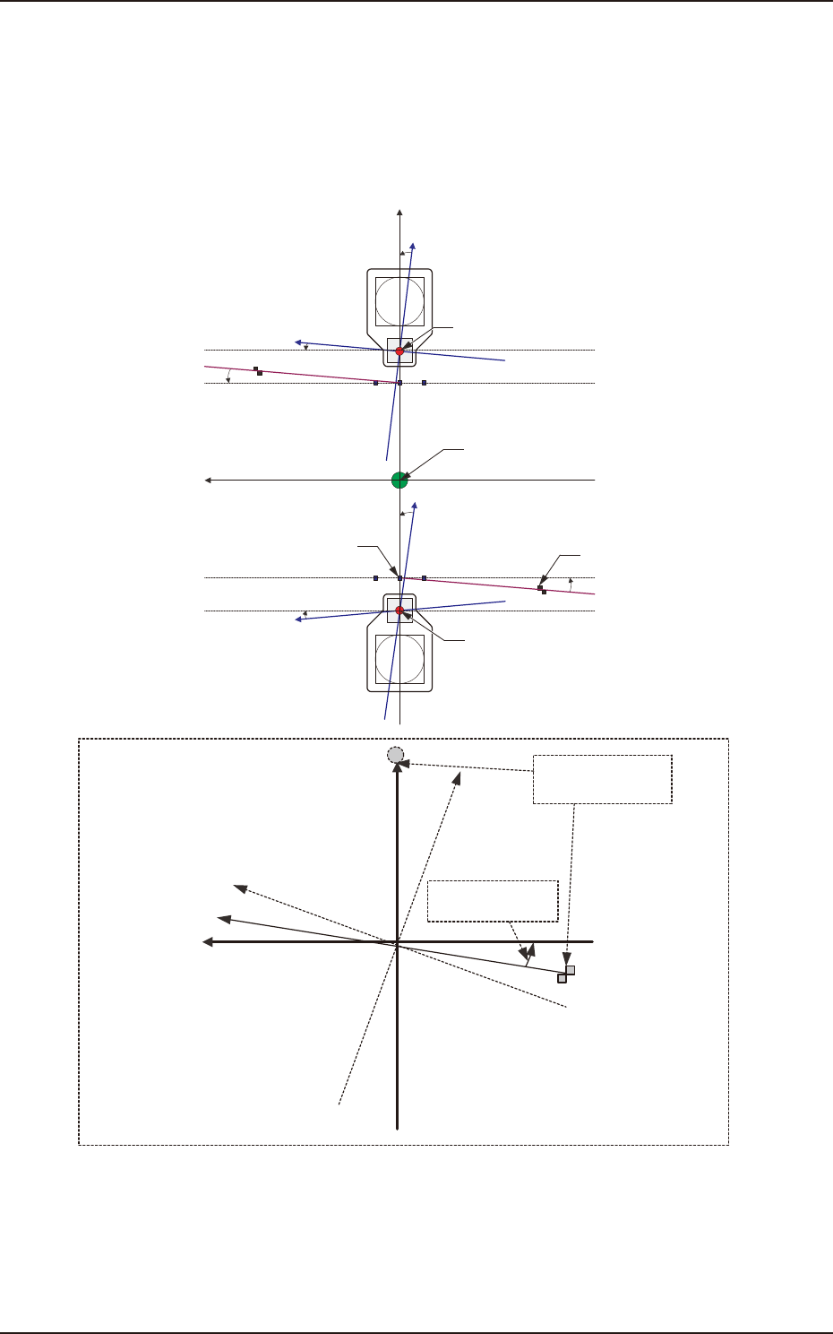
[3] Rectangular Angle X [deg]
These parameters represent the amount of angular deviations (X directions) of the mark on the
machine in comparison with the X directions in the machine reference coordinate system.
The set parameters are used to check the three marks on the area of the machine where only a little
positional change can be made according to temperature changes and adjust the beam X/Y axes
such that they can cross at right angles.
Xm(+)
Ym(+)
Yb(+)
Xb(+)
Yb(+)
Xb(+)
Xm'
Machine Reference
Coordinate System
Mark Coordinate
System
Beam Coordinate
System
Mark on Machine
Rectangular Angle
X [deg]
Head Origin
Pm. Machine Reference
Coordinate Origin
Standard Mark 2
Head Origin
Standard Mark 1
Xm-Ym
Xb-Yb
: Machine Reference
Coordinate System
: Real Beam Coordinate
System
F3B28