EUKYX-199-3100_G5S2_Instruction_Vol3_E.pdf - 第193页
EUKYX 2-45 199-3100 2.7 Nozzle Stocker 2.7 . 1 1 - 1 to 1 - 4, 2- 1 to 2 - 4 Pressi ng the [1 - 1] tab on the "Nozz le Stock er " wi ndow di spl ays the fol lowi ng window . (a) The same tab shee t appears from…
EUKYX
2-44199-3100
2.7 Nozzle Stocker
2.7 Nozzle Stocker
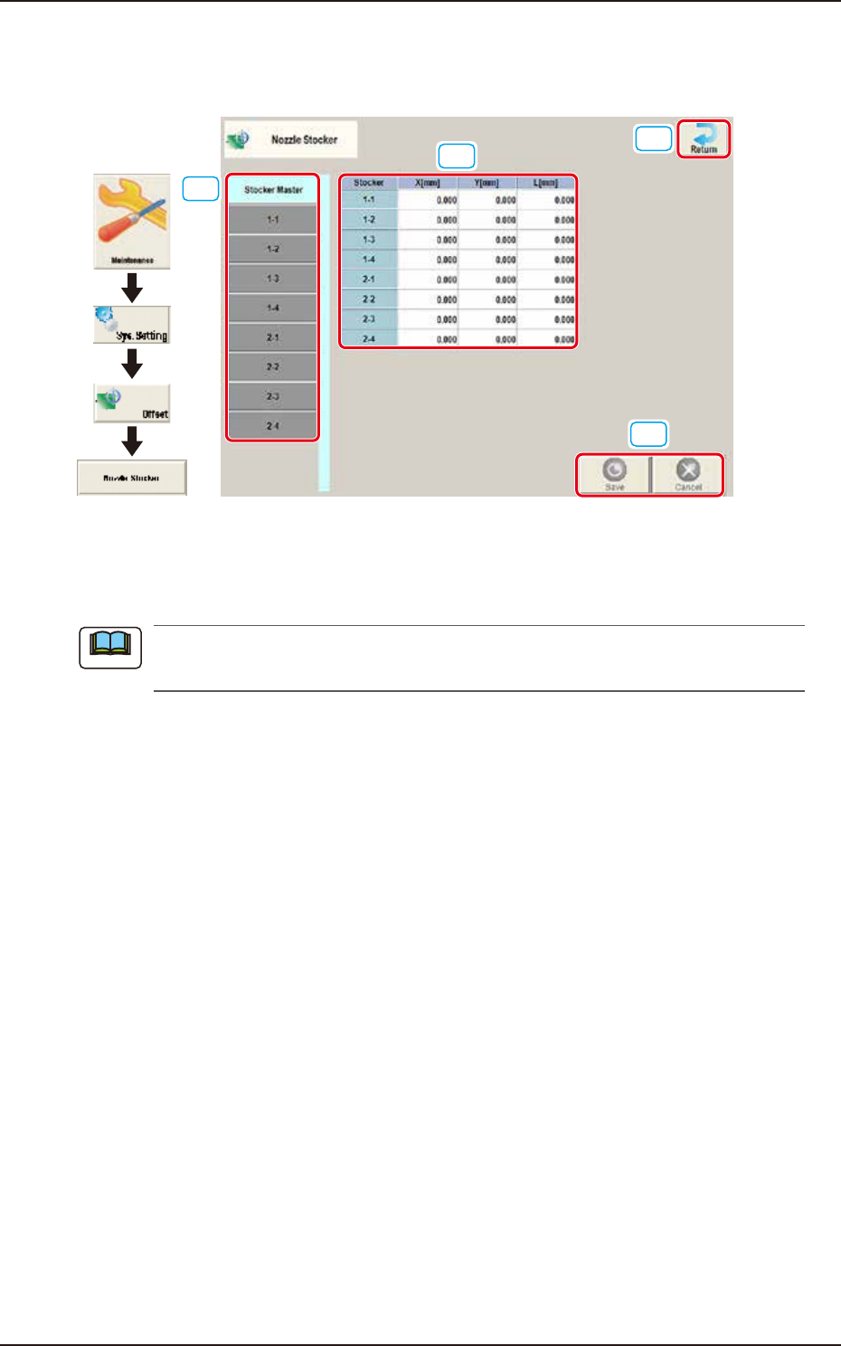
Pressing the [Nozzle Stocker] button on the "Offset Data" window displays the following window.
[4]
[2]
[1]
[3]
Graphic
Development
F3B56
[1] Offset button
When this button is pressed, the offset data for the selected tab is displayed.
When the [Stocker Master] tab is pressed, the set values of 1-1 through 1-4 and 2-1 through
2-4 are displayed.
[2] Offset Data Display Section
In this section, the offset data selected in step [1] is displayed.
[3] [Return] button
When this button is pressed, the window returns to the “Offset Data” window.
[4] [Save] button
When this button is pressed, the input data is saved.
[Cancel] button
When this button is pressed the input data is cancelled and the window returns to the saved data.
Note
EUKYX
2-45199-3100
2.7 Nozzle Stocker
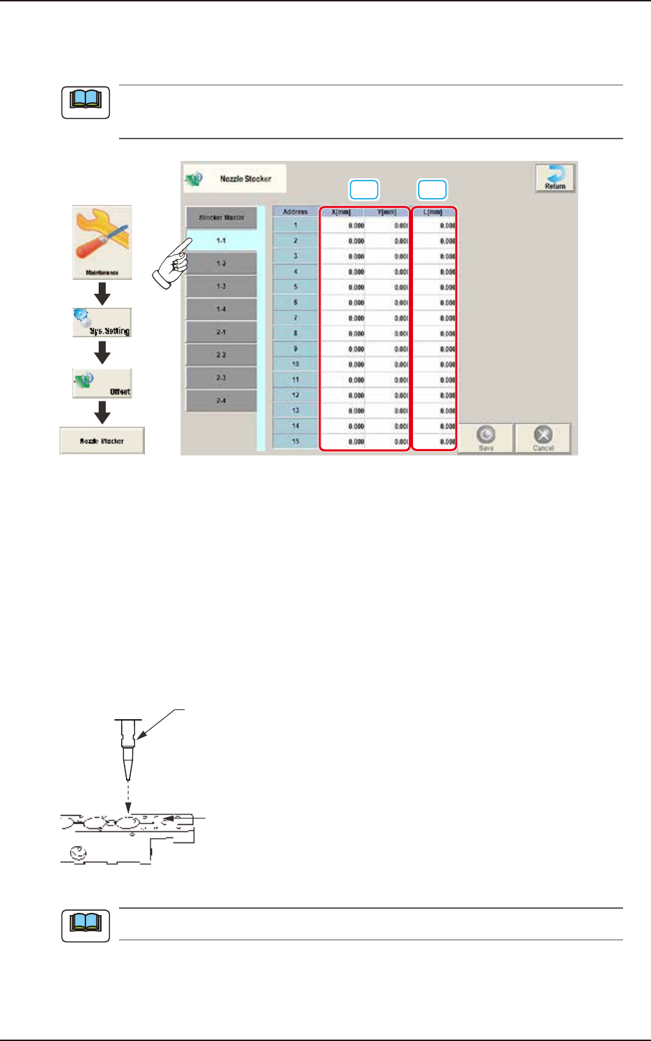
2.7.1 1-1 to 1-4, 2-1 to 2-4
Pressing the [1-1] tab on the "Nozzle Stocker" window displays the following window.
(a) The same tab sheet appears from [1-2] to [2-4].
(b) The tab sheet may look different, depending on which options are selected.
[1]
[2]
Graphic
Development
F3B57
[1] X (Horizontal) / Y (Vertical) [mm]
This offset data is used to adjust the nozzle change position deviation from the nozzle stocker unit
position designed value based on the PCB locating base XY coordinates (Machine Reference XY
Coordinates: Origin P0).
The Machine Reference XL Coordinates are set to the reference values.
When positive (+) value is set for the offset value, the nozzle change position is changed to
directions X(+) and Y(+).
[2] L (Height) [mm]
When a value is entered with a plus (+) sign, the nozzle change position (height) is changed in the L
(+) direction, concluding that the descending stroke has increased.
Nozzle
Nozzle Mounting Level
(Upper Surface of Nozzle Stocker Block)
L(+)
F3B58
The above "L" is effective only in the master nozzle.
Note
Note
EUKYX
2-46199-3100
2.8 PCB Recog
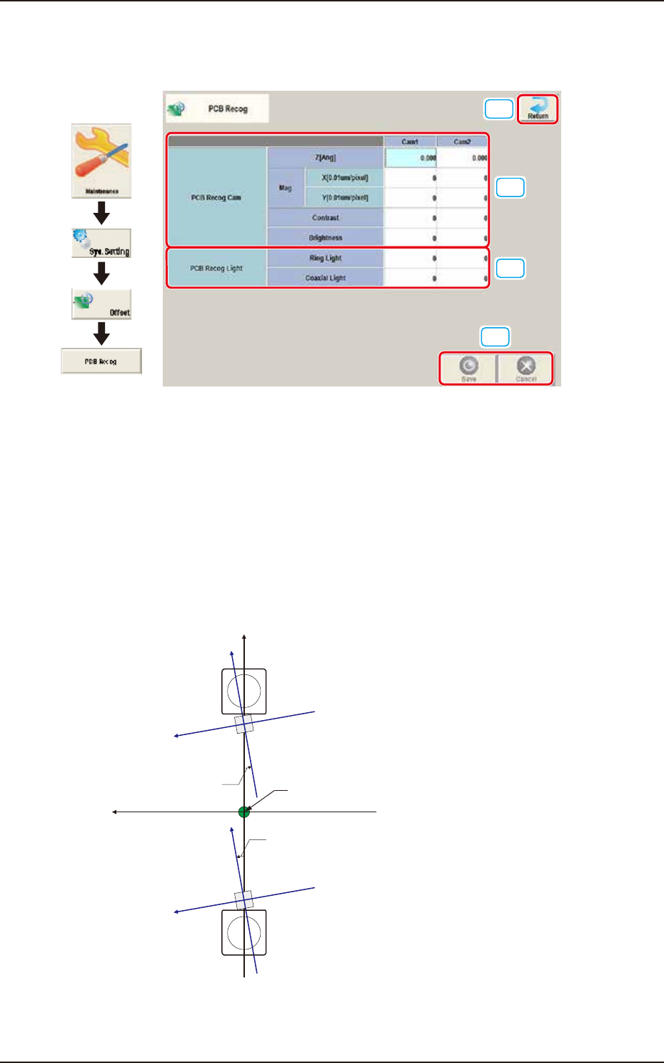
2.8 PCB Recog
Pressing the [PCB Recog] button on the "Offset Data" window displays the following window.
[1]
[2]
[4]
[3]
Graphic
Development
F3B59
Set the following offset values for each camera.
[1] PCB Recog Cam
The set parameters are used to adjust the horizontal tilt of PEC recognition camera.
Z (Angle) [deg]
Set the parameters representing the angular deviations in the scanning coordinates of the
PEC recognition cameras based on the machine reference X/Y coordinates (Xm-Ym). When
the camera scanning coordinates are shifted counterclockwise to the machine reference X/Y
coordinate system, a plus sign must be affixed to each offset data.
Xm(+)
Ym(+)
Yc(+)
Xc(+)
Yc(+)
Xc(+)
Angle of PEC Recognition Camera
Xm-Ym
Xc-Yc
Angle of PEC Recognition Camera
Pm. Machine Reference
Coordinate Origin
: Machine Reference
Coordinate System
: PEC Recognition
Coordinate System
F3B60