EUKYX-199-3100_G5S2_Instruction_Vol3_E.pdf - 第202页
EUKYX 2-54 199-3100 2.1 1 Unit Offset 2. 1 1 Unit Of fs et Pressi ng the [Uni t Of fse t] but ton on the "Of f set Data" w indo w di spl a ys the fol lowi ng wi ndow . Graphic Development F3B69 Thi s s et ting …
EUKYX
2-53199-3100
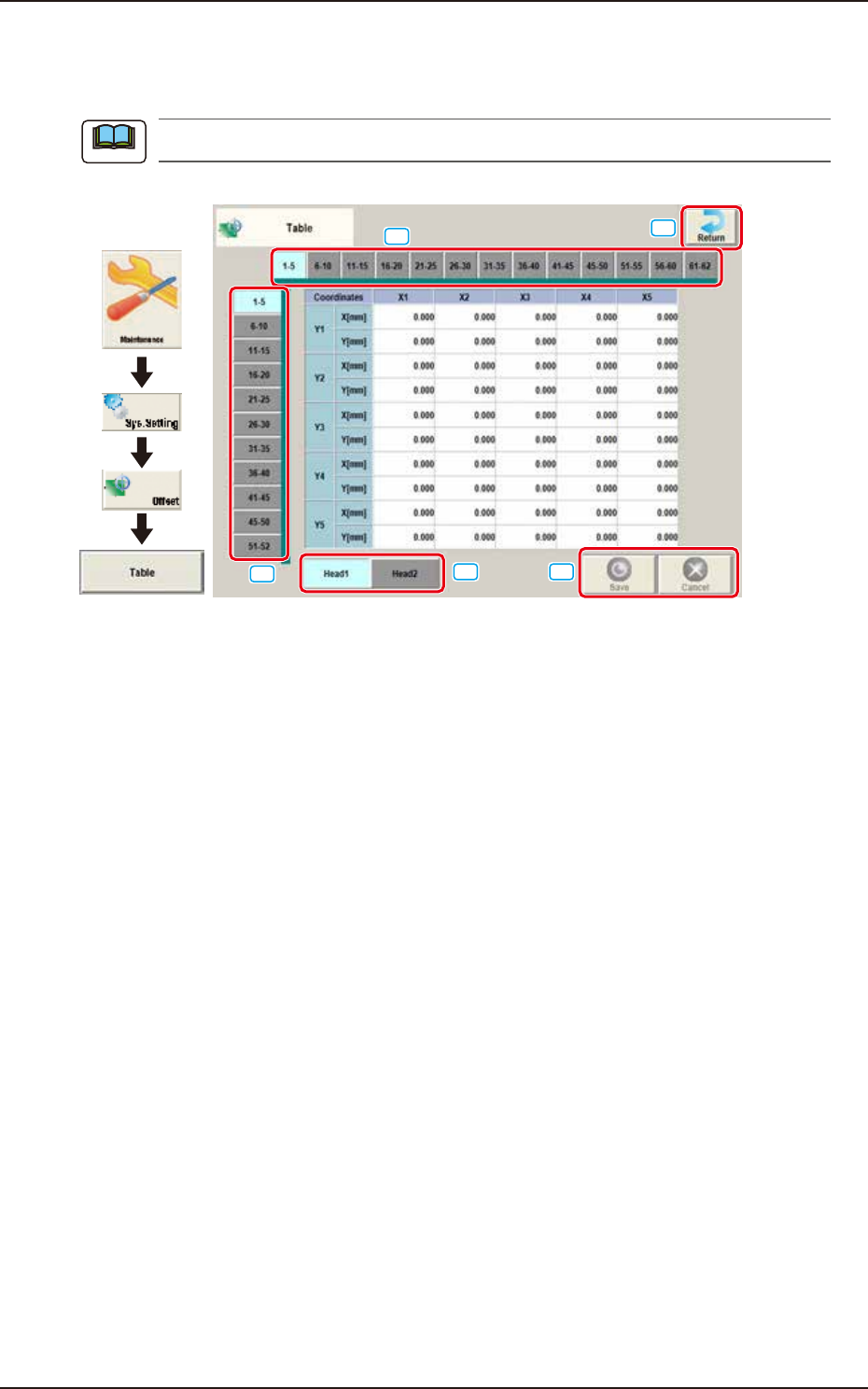
2.10 Table
2.10 Table
Pressing the [Table] button on the "Offset Data" window displays the following window.
As for the "Head 2" tab sheets, the same contents as the "Head 1" tab sheet are displayed.
Graphic
Development
[1]
[2]
[3]
[4]
[5]
F3B68A
Enter the amount of deviation based on the specified distance when Head 1 has moved as far as the
specified distance (each grid point, X Direction: X1 through X40, Y Direction: Y1 through Y40) from
the PCB positioning reference.
These values are calculated automatically through the teaching operation and entered in each text
box.
[1] Head Select Tab
Using this tab, the head to be input is selected.
[2] Direction "X" Select Tab
Using this tab, the point on the grid in the direction "X" for the selected tab, is displayed.
[3] Direction "Y" Select Tab
Using this tab, the point on the grid in the direction "Y" for the selected tab, is displayed.
[4] [Return] button
Returns to the “Offset Data“ window.
[5] [Save] button
Saves the entered data.
[Cancel] button
Cancels the entered data and returns to the saved data.
Note
EUKYX
2-54199-3100
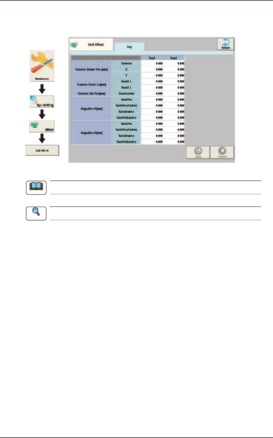
2.11 Unit Offset
2.11 Unit Offset
Pressing the [Unit Offset] button on the "Offset Data" window displays the following window.
Graphic
Development
F3B69
This setting is used as an option.
Refer to "GS-FP600 Multi-Layer Tray Feeder" for details.
Note
Reference
EUKYX
2-55199-3100
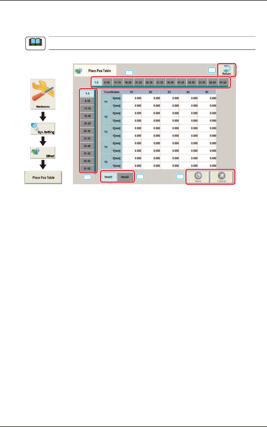
2.12 Place Pos Table
2.12 Place Pos Table
Pressing the [Place Pos Table] button on the "Offset Data" window displays the following window.
The display of the [Head 2] is same as the [Head 1].
Graphic
Development
[1]
[2]
[3]
[4]
[5]
F3B70
The window shows the place position table offset value from nozzle tip as a reference point. Place
components on a glass board in 10
×
10 mm grid pattern. At this time, the angle of head that picks
and mounts with nozzle 1 is 0 degree. Then enter the measured values (X and Y) on the window.
[1] Head Select Tab
The head to be input is selected.
[2] Direction “X” Select Tab
The point on the grid in the direction “X” for the selected tab, is displayed.
[3] Direction “Y” Select Tab
The point on the grid in the direction “Y” for the selected tab, is displayed.
[4] [Return] button
Returns to the “Offset Data“ window.
[5] [Save] button
Saves the entered data.
[Cancel] button
Cancels the entered data and returns to the saved data.
Note