EUKYX-199-3100_G5S2_Instruction_Vol3_E.pdf - 第211页
EUKYX 2-63 199-3100 3.1 Auto Ope. Set-up [2] Dclr of b ackup axis Select the d ecelera tion setting eac h for bac kup a xis from the fo l lowi ng items. Full Spee d, 1 0% Dec r , 20% Dec r , 3 0% Dec r , 40% De cr , 50% …
EUKYX
2-62199-3100
3.1 Auto Ope. Set-up
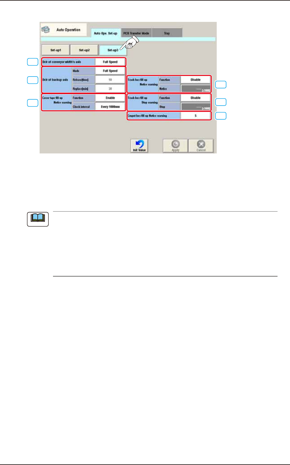
• Set-up 3
[1]
[3]
[2]
[4]
[5]
[6]
F3B75A
[1] Dclr of conveyor width's axis
Select the deceleration setting each for conveyor width axis from the following items.
Full Speed, 10% Decr, 20% Decr, 30% Decr, 40% Decr,
50% Decr, 60% Decr, 70% Decr, 80% Decr, 90% Decr
When the ambient temperature is lower than the specified temperature (20°C ± 10°C), perform
the deceleration setting each for the conveyor width axis and backup axis referring to the
following setting standard.
• Setting Standard based on Ambient Temperature
10°C or more : Full Speed
7 to 10°C : 50%
Less than 7°C : 70%
Note

EUKYX
2-63199-3100
3.1 Auto Ope. Set-up
[2] Dclr of backup axis
Select the deceleration setting each for backup axis from the following items.
Full Speed, 10% Decr, 20% Decr, 30% Decr, 40% Decr,
50% Decr, 60% Decr, 70% Decr, 80% Decr, 90% Decr
When the ambient temperature is lower than the specified temperature (20°C ± 10°C), perform
the deceleration setting each for the conveyor width axis and backup axis referring to the
following setting standard.
• Setting Standard based on Ambient Temperature
10°C or more : Full Speed
7 to 10°C : 50%
Less than 7°C : 70%
• Release [time]
When the set No. of backup axis operations is completed, the backup axis deceleration setting is
cancelled.
Set Value Range : 0 to 99
• Replace [min]
When the set time period, standby time period and stop time period have been elapsed, the
deceleration control is performed again.
[3] Cover tape fill up Notice warning Function
The cut tape debris amount is calculated based on the counted number decided based on
the component reload data (Tape feed, Feed pitch and Type) on the component library data
and the cut tape FULL alarm is issued or machine stop operation is performed. Set "Enable"
or "Disable" in this selection box.
Check interval
The interval is selected from the following items.
Every 1000 mm / Every 500 mm / Every 300 mm
[4] Trash box fill up Notice warning
For the Trash box fill-up notice warning, the following items are set.
Function
“Enable” or “Disable” is set in this selection box.
Notice [×1000]
Count : 1 to 9999 [×1000]
Initial value : 900 [×1000]
[5] Trash box fill up Stop warning
For the Trash box fill-up stop warning, the following items are set.
Function
“Enable” or “Disable” is set in this selection box.
Stop [×1000]
Count : 1 to 9999 [×1000]
Initial value : 1350 [×1000]
[6] Cmpnt box fill up Notice warning
The component discharge box full count is set in this data box.
Note
EUKYX
2-64199-3100
3.2 PCB Transfer Mode
3.2 PCB Transfer Mode
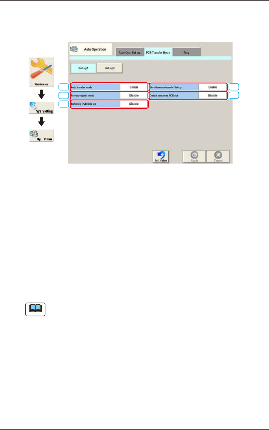
Pressing the [PCB Transfer Mode] tab on the "Auto Operation" window displays the following
window.
[4]
[5]
[1]
[2]
[3]
Graphic
Development
F3B76A
• Set-up 1
[1] Auto transfer mode
Whether or not the automatic transfer mode in the PCB discharge operation is used, is set in
this selection box.
Enable
The discharge of the PCB where the components have been placed, on the PCB positioning
unit, is performed at the same time of the transfer of the next PCB to the PCB positioning unit.
Disable
The discharge of the PCB (finished PCB) to the output machine is performed in this PCB
transfer mode, when the components have been placed on the PCB on the PCB positioning
unit and there is no PCB on the buffer section and the conveyor movement is not started.
[2] Furnace signal check
Set "Disable" or Enable" to determine whether or not the furnace signal check function should be
activated.
When "SMEMA" is set in the "Input mode" text box of the label "Input Setup" or in the "Output
mode" text box of the label "Output Setup", this function cannot be used.
[3] Buffering PCB Size Up
It is activated when “Enable“ is selected for “Simultaneous transfer Set-up“.
Select “Disable” or Enable” for buffering the PCB X size from 280 to 410 mm to the supply
conveyor.
[4] Simultaneous transfer Set-up
Select “Enable” or “Disable” to determine whether or not the PCB transfer should be made
simultaneously between the input and positioning conveyors and between the positioning and
output conveyors.
[5] Output conveyor PCB out
Set “Disable” or “Enable” to determine whether or not a disengaged PCB should be detected in the
output conveyor section.
Note