EUKYX-199-3100_G5S2_Instruction_Vol3_E.pdf - 第186页
EUKYX 2-38 199-3100 2.6 Nozzle 2.6. 1 Nozzle Le vel A Pressi ng the [Nozzl e Lev el A] tab on the "Nozz le" wi nd ow di spla ys t he fol lowi ng window . [1] [2] Graphic Development F3B47A [1] N o z z l e In th…
EUKYX
2-37199-3100
2.6 Nozzle
2.6 Nozzle
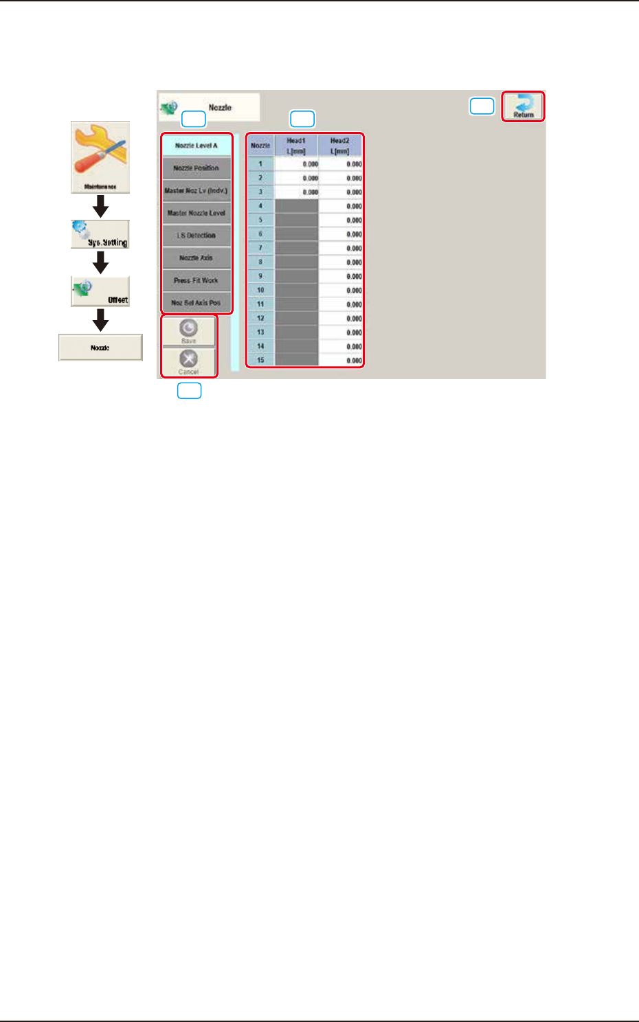
Pressing the [Nozzle] button on the "Offset Data" window displays the following window.
[1] [2]
[3]
[4]
Graphic
Development
F3B46A
[1] Offset button
When this button is pressed, the offset data for the selected tab is displayed.
[2] Offset Data Display Section
In this section, the offset data selected in step [1] is displayed.
[3] [Return] button
When this button is pressed, the window returns to the "Offset Data" window.
[4] [Save] button
When this button is pressed, the input data is saved.
[Cancel] button
When this button is pressed the input data is cancelled and the window returns to the saved data.
EUKYX
2-38199-3100
2.6 Nozzle
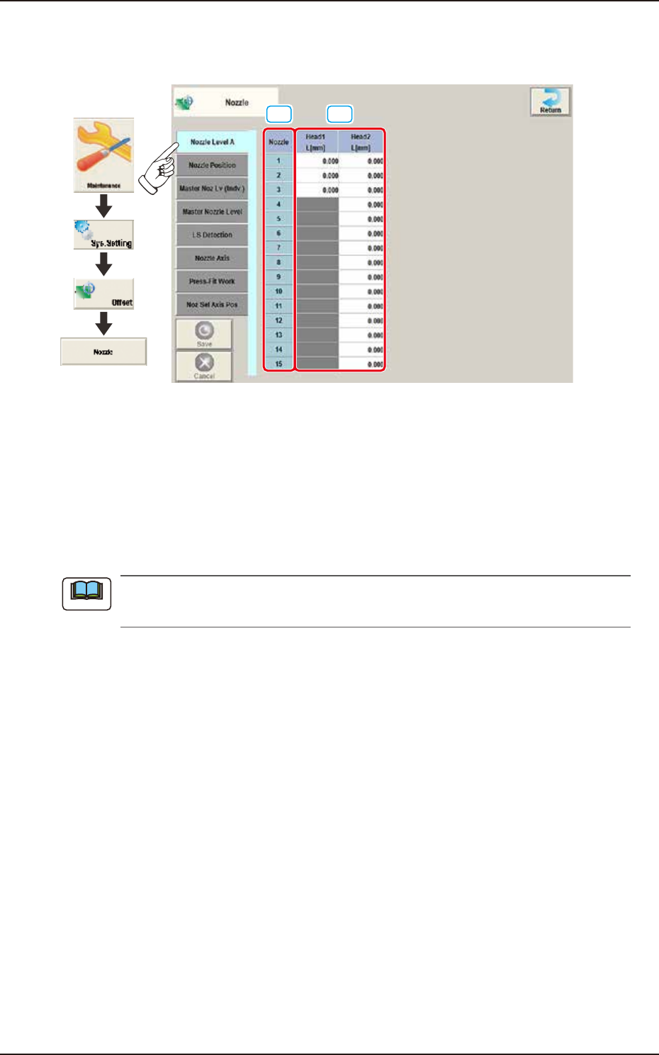
2.6.1 Nozzle Level A
Pressing the [Nozzle Level A] tab on the "Nozzle" window displays the following window.
[1] [2]
Graphic
Development
F3B47A
[1] Nozzle
In this section, each nozzle No. is displayed.
[2] Head 1 and Head 2
L (Height) [mm]
Each parameter indicates the offset of the bottom level of the normal nozzles on each individual
heads. Measure each nozzle bottom level with a side view camera while the nozzle U/D axis is
zeroed and save the difference between the level and the master nozzle level offset.
These parameters are calculated using the formula "Nozzle Level Offset = Master Nozzle
Level - Measured Value of Normal Nozzle Level".
Note
EUKYX
2-39199-3100
2.6 Nozzle
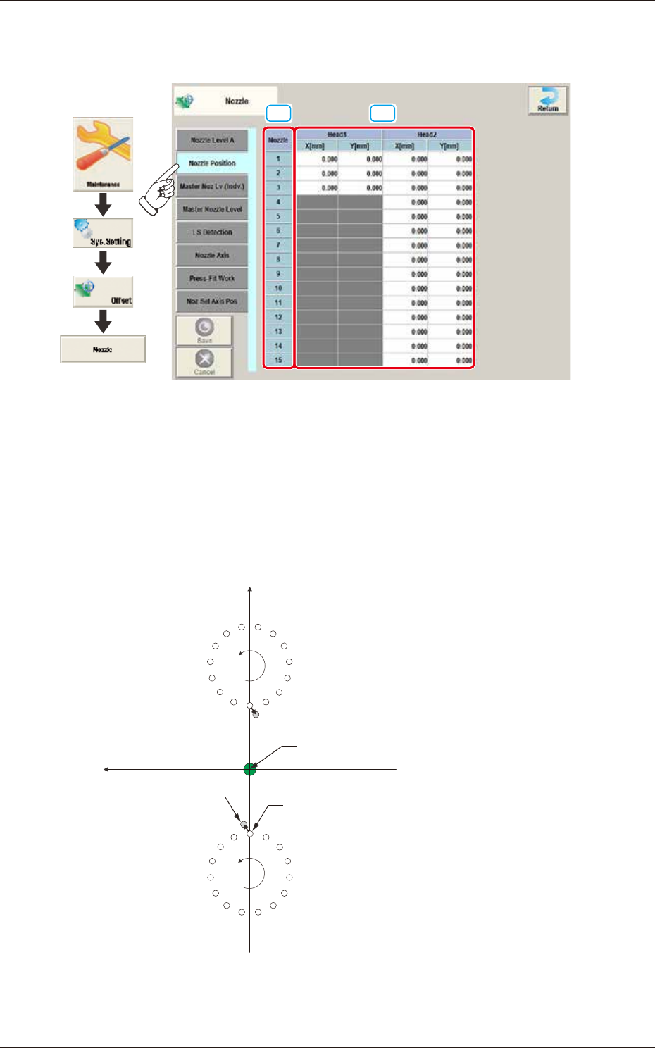
2.6.2 Nozzle Position
Pressing the [Nozzle Position] tab on the "Nozzle" window displays the following window.
[1] [2]
Graphic
Development
F3B48A
[1] Nozzle
In this section, each nozzle No. is displayed.
[2] Head 1 and Head 2
X (Horizontal) and Y (Vertical) [mm]
Displayed is the offset data for the lowest levels of the normal nozzles on the heads. The lowest
level of each nozzle is measured by the component recognition camera and the difference between
the actual and recognized levels is compensated for.
Xm(+)
Ym(+)
Xm-Ym :
DD (+)
DD (+)
Nozzle Designed Position
Real Nozzle Position
Pm. Machine Reference
Coordinate Origin
1
2
3
4
5
6
7
8
9
10
11
12
13
14
15
1
2
3
4
5
6
7
8
9
10
11
12
13
14
15
Machine Reference
Coordinate System
F3B49