EUKYX-199-3100_G5S2_Instruction_Vol3_E.pdf - 第205页
EUKYX 2-57 199-3100 3.1 Auto Ope. Set-up 3. 1 Auto Ope . Set -up Pressi ng the [Aut o Ope S et-up] ta b on the " Auto Ope rati on" window d ispla ys the fol lo win g wi ndow . Graphic Development [1] [2] [3] F3…
EUKYX
2-56199-3100
3. Auto Operation
3. Auto Operation
Pressing the [Sys. Setting] - [Ope. Palam] buttons displays the following window.
Graphic
Development
F3B71A
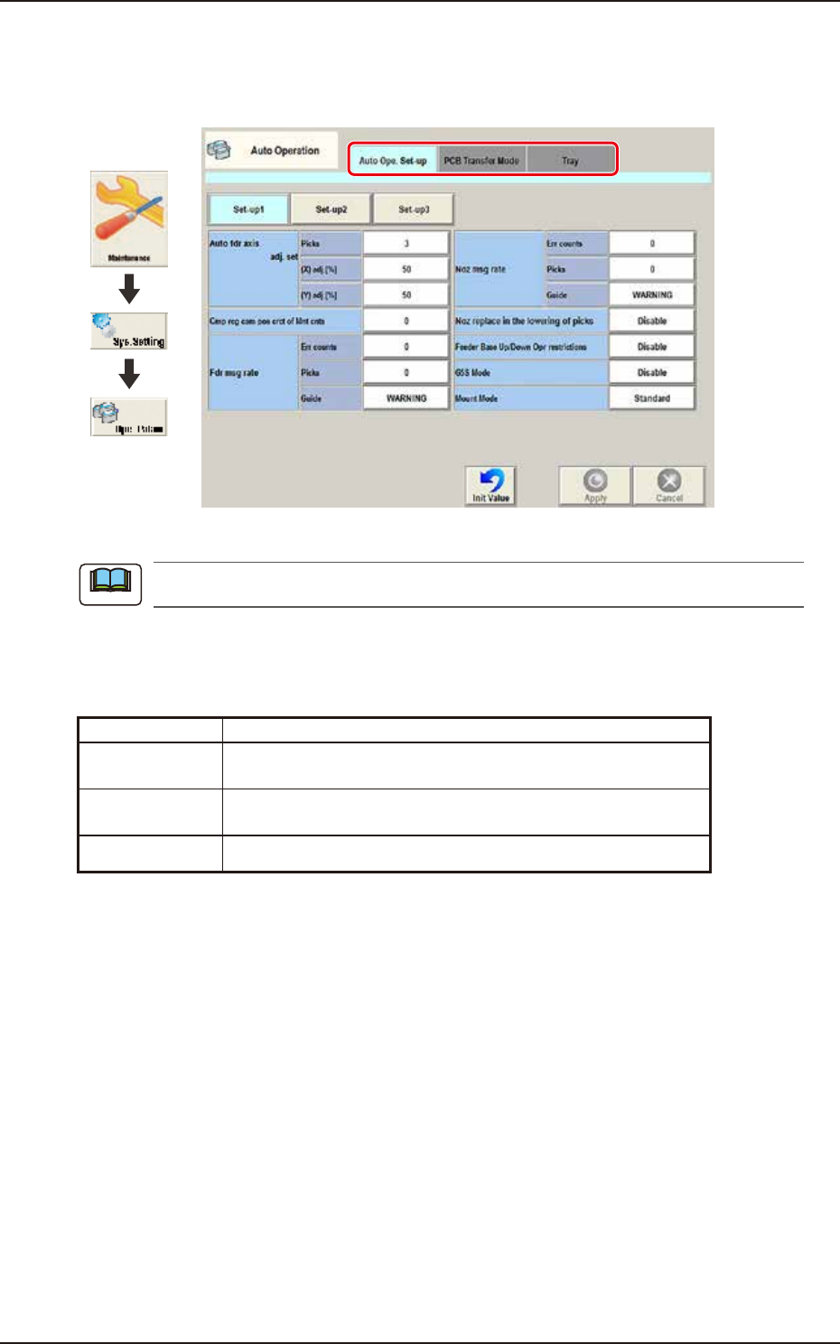
The tab sheet may look different, depending on which options are selected.
[1] Tab sheet
The "Auto Operation" window is provided with the following 3 tabs. When each tab is pressed, the
corresponding tab sheet appears.
Tab Description
Auto Ope.
Set-up
Set various types of parameters related to the automatic
operation of the machine.
PCB Transfer
Mode
Set the operation mode of the input and output machines and the
requirements for PCB transfer and positioning operations.
Tray Set the information of tray matrix when a tray unit is used.
Note
EUKYX
2-57199-3100
3.1 Auto Ope. Set-up
3.1 Auto Ope. Set-up
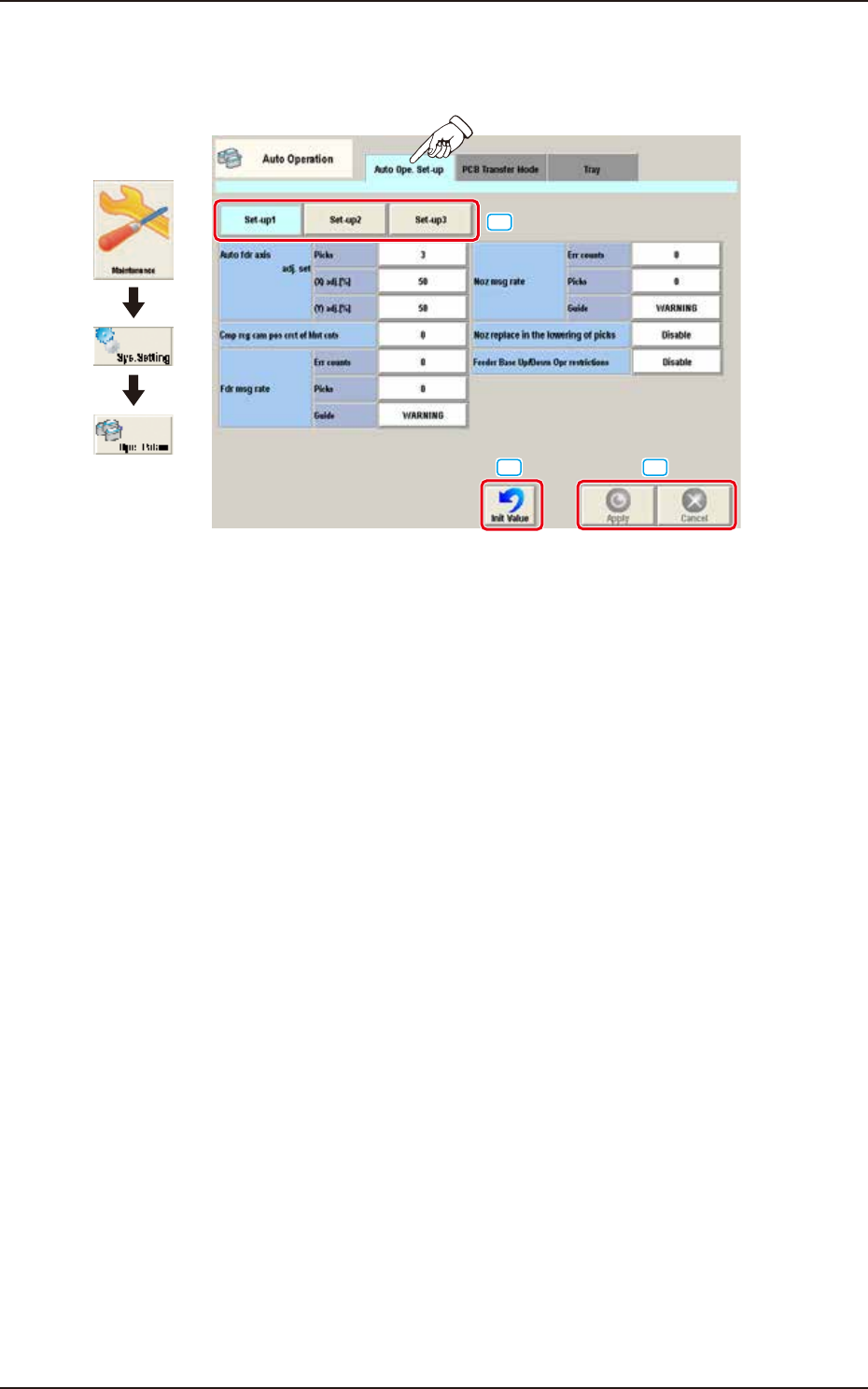
Pressing the [Auto Ope Set-up] tab on the "Auto Operation" window displays the following window.
Graphic
Development
[1]
[2]
[3]
F3B72A
[1] Set-up Change Button
The window is changed over from "Set-up 1", "Set-up 2", or "Set-up 3".
[2] Init Value Button
When this button is pressed, the auto operation set-up is initialized.
[3] [Apply] button
When this button is pressed, the input data is applied.
[Cancel] button
When this button is pressed, the input data is cancelled and the window returns to the save data.
EUKYX
2-58199-3100
3.1 Auto Ope. Set-up
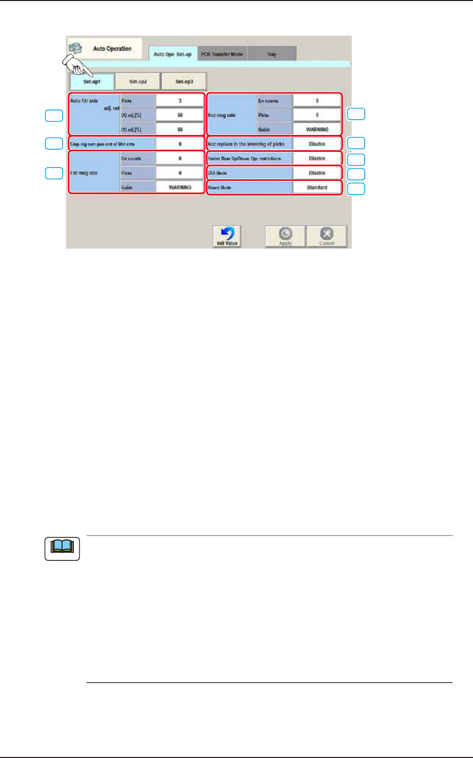
• Set-up 1
[1]
[2]
[3]
[4]
[5]
[6]
[7]
[8]
F3B73A
[1] Auto fdr axis adj. set
picks [times]
Set the total number of collected samples when data is updated or changed.
(X) adj. [%]
Set the feedback coefficient of mean of X-direction deviation in this data box.
Set Value Range: 10 to 90
(Y) adj. [%]
Set the feedback coefficient of mean of Y-direction deviation in this data box.
Set Value Range: 10 to 90
[2] Cmp rcg cam pos crct of Mnt cnts [times]
Press the value to display the “Ten-key Input” window and enter one of the following values.
“0” : No automatic correction operation is performed for each number of
components to be placed.
“1” to “9999” : Correction is made according to the specified number of components to
be placed.
(a) When “1” to “9999” is set in the “Cmp rcg cam pos crct of Mnt cnts” box, the corrective
actions take place automatically before the PCB is transferred to the PCB positioning
section and the component recognition operation is performed.
(b) When the number of components (components to be placed on a production PCB) per
beam is smaller than the set number of components, the corrective actions do not take
place in the middle of placement operation.
Because the internal counter for interval monitoring is cleared through the above-
described corrective actions (the actions which take place during PCB positioning), no
corrective actions take place in compliance with the number of components to be placed
on several PCBs.
Note