EUKYX-199-3100_G5S2_Instruction_Vol3_E.pdf - 第71页
EUKYX 1-22 199-3100 4.3 CONVEYOR 4.3. 2 PCB Stp r . The adj ust ment for ea ch PCB stopper is per formed on this tab sheet. [1] [2] [3] Graphic Development F3A21 [ 1 ] PCB St opp er Sel ectio n Butt ons Select the P CB s…
EUKYX
1-21199-3100
4.3 CONVEYOR
[3] Conveyor Setup Buttons
When the target position is moved, the conveyor width adjustment values are setup using the
following buttons.
[Tgt Wd] Button
When this button is pressed, the "Tgt Wd" input window appears. When a value is entered
and the [SET] button is pressed, the target value is setup.
[Clearance] Button
When this button is pressed, the "Clearance" input window appears.
Set the data for the conveyor width to have some margin from the PCB size set in the pattern
program. The actual conveyor width is "PCB Size" (Target Width) + "Clearance"
(Recommended Value: 0.5 mm).
When a value is entered and the [SET] button is pressed, the clearance value is setup.
[Base Pos] Button
When this button is pressed, the "Base Pos" input window appears. In this window, the base
position adjusting data is setup. When the value is entered and the [SET] button is pressed,
the base position is setup.
■
Conveyor Width Manual Setup
When the conveyor width is set up, use the following procedure.
(1) In each input window displayed by pressing the [Tgt Wd], [Clearance] and [Base Pos]
buttons for the "Conveyor" width, enter the data parameter for each item.
(2) Within 10 seconds after pressing the [Tgt Wd] button, press the [START] button on the
operation panel. (The conveyor width will be adjusted to ("Tgt Wd" value + "Clearance"
value). Also, the conveyor will be moved to the set base position.)
Procedure
EUKYX
1-22199-3100
4.3 CONVEYOR
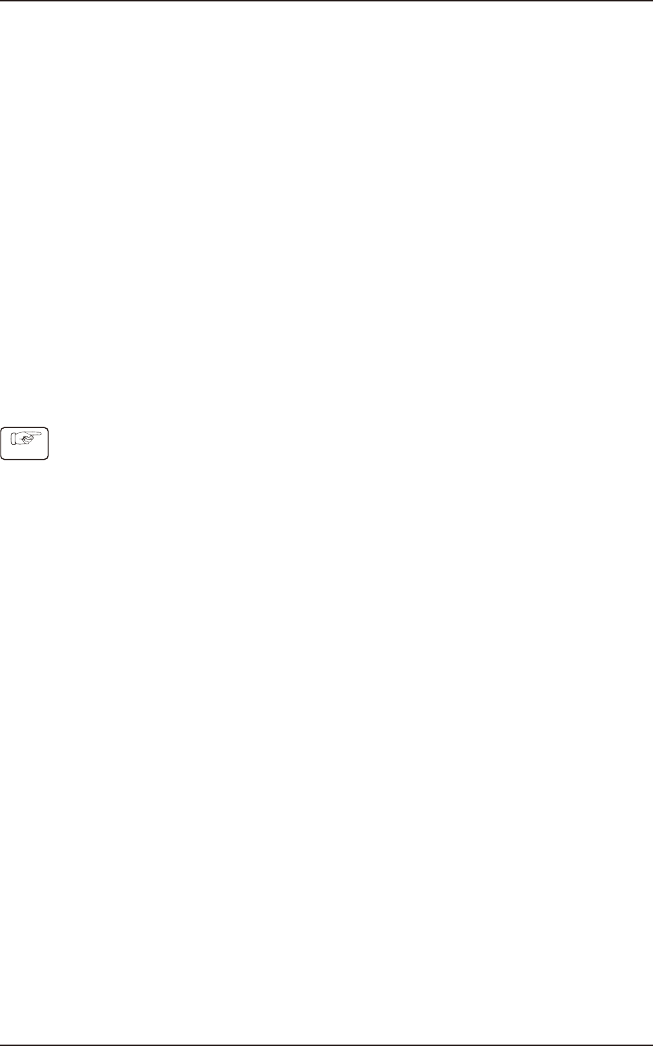
4.3.2 PCB Stpr.
The adjustment for each PCB stopper is performed on this tab sheet.
[1]
[2] [3]
Graphic
Development
F3A21
[1] PCB Stopper Selection Buttons
Select the PCB stopper to be operated.
[2] Control Switch
[UP] Button
When the [START] button is pressed on the operation panel within 10 seconds after this
button is pressed, the selected PCB stopper is moved up.
[DOWN] Button
When the [START] button is pressed on the operation panel within 10 seconds after this
button is pressed, the selected PCB stopper is moved down.
[3] Status Display
Result
In this data box the PCB stopper operation result is displayed as "OK" or "NG".
Mode
In this data box the PCB stopper present status is displayed as "UP" or "Down".
Time [ms]
In this data box the PCB stopper operation time is displayed.
EUKYX
1-23199-3100
4.3 CONVEYOR
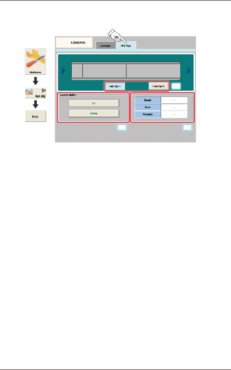
4.3.3 X Axis grease up
Follow the instructions on the window to apply grease to X-axis.
Graphic
Development
F3A95
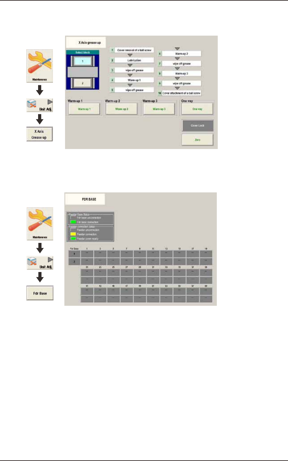
4.3.4 FDR BASE
The status colors show the connection status of feeder base and feeder.
Graphic
Development
F3A96