EUKYX-199-3100_G5S2_Instruction_Vol3_E.pdf - 第158页
EUKYX 2-10 199-3100 2.1 Device Offset 2 .1.1 0 M a r k - P i c k - u p Thi s window is not displayed wh en the multi -f unctional head is se lect ed. Pressi ng the [Mark-Pi ck-up] tab on the "D evi ce Of fset "…
EUKYX
2-9199-3100
2.1 Device Offset
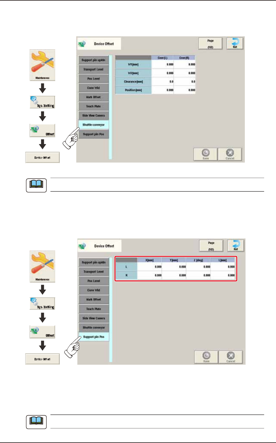
2.1.8 Shuttle conveyor
Pressing the [Shuttle conveyor] tab on the "Device Offset" window displays the following window.
Graphic
Development
F3B13A
This setting is used as an option.
2.1.9 Support pin Pos
Pressing the [Support pin Pos] tab on the “Device Offset” window displays the following window.
Graphic
Development
F3B14A
[1] L / R
X [mm], Y [mm], Z [deg], L [mm]
These offset parameters are to be corrected when the support pin data is converted. These offset
parameters are calculated automatically in the support pin teaching operation.
When this teaching is performed, the dedicated teaching pins are required.
Note
Note

EUKYX
2-10199-3100
2.1 Device Offset
2.1.10 Mark-Pick-up
This window is not displayed when the multi-functional head is selected.
Pressing the [Mark-Pick-up] tab on the "Device Offset" window displays the following window.
[1] [2]
Graphic
Development
F3B15A
[1] XY Dclr [Pick-up]
0 [%] to 45 [%]
The XY speed reduction rate is displayed in these data boxes.
[2] Head 1 / 2
X [mm] / Y [mm]
The deviation for the head X, Y when the head is moved from the reference mark to the pick-up
position, is corrected based on the XY speed reduction rate.
Note
EUKYX
2-11199-3100
2.1 Device Offset
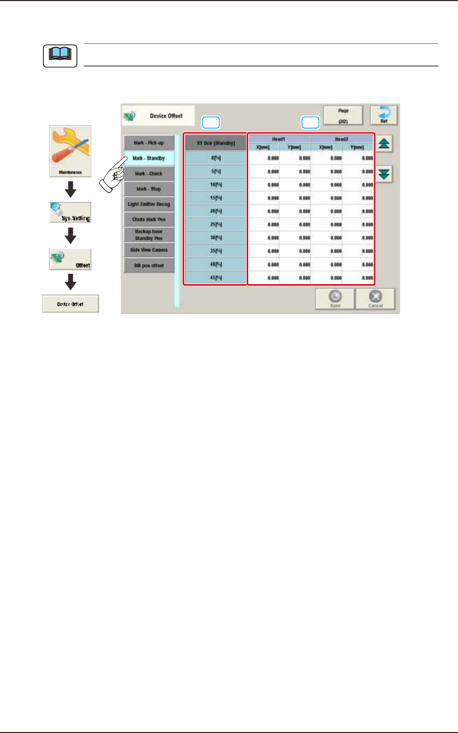
2.1.11 Mark-Standby
This window is not displayed when the multi-functional head is selected.
Pressing the [Mark-Standby] tab on the "Device Offset" window displays the following window.
[1] [2]
Graphic
Development
F3B16A
[1] XY Dclr [Standby]
0 [%] to 45 [%]
The XY speed reduction rate is displayed in these data boxes.
[2] Head 1, 2
X [mm], Y [mm]
The deviation for the head X, Y when the head is moved from the reference mark to the waiting
position, is corrected based on the XY speed reduction rate.
Note