EUKYX-199-3100_G5S2_Instruction_Vol3_E.pdf - 第63页
EUKYX 1-14 199-3100 4.1 NOZ. CHNG. • Procedu re for Noz zle St orage (a ) When the high- sp eed nozzle are used t ogether w ith the middle- size odd shaped nozzle, the m iddle-s ize odd shaped nozzle mus t be store d pri…
EUKYX
1-13199-3100
4.1 NOZ. CHNG.
[4] "Control Switch" Group Box
The following operation buttons are arranged.
When the [START] button on the operation panel is pressed within 10 seconds after the each
operation button, the selected action takes place.
[Reset Nozzle] Button
When selected, this button stores the specified nozzle in the nozzle stocker.
When this button is pressed, the background color turns green, indicating that the head
selection button is set active.
[Set Nozzle] Button
When selected, this button picks up the selected nozzle from the nozzle stocker and
attaches it to the specified nozzle No. position.
When this button is pressed, the background color turns green, indicating that the head and
nozzle (nozzle stocker) selection buttons are set active.
[5] Nozzle Stocker tab
Using this tab, the nozzle stocker to be opened or closed and the nozzle housed in the nozzle
stocker, are designated.
Selecting the nozzle stocker using the nozzle stocker select tab and pressing the button for an
appropriate nozzle, designates the nozzle to be used.
For the stocker for which the skip has been set, a message is displayed and the stocker can not
be operated.
Note
EUKYX
1-14199-3100
4.1 NOZ. CHNG.
• Procedure for Nozzle Storage
(a) When the high-speed nozzle are used together with the middle-size odd shaped nozzle,
the middle-size odd shaped nozzle must be stored prior to the others.
When the machine starts to store the high-speed nozzle prior to the middle-size odd
shaped nozzle, a dialog box opens, prompting that the middle-size odd shaped nozzle
must be stored first and indicating that the high-speed nozzle cannot be stored.
(b) Do not house the nozzle while the head picks up a component. Doing so breaks the
vacuum and the component drops.
(1) Press the head (one of the head selection buttons) holding the nozzle desired to be stored.
(The background color of the selected button turns light blue.)
(2) Select the nozzle (one of the nozzle allocation No. selection buttons) holding the nozzle
desired to be stored.
(The background color of the selected button turns light blue.)
(3) To select a nozzle stocker different from the original one, press the nozzle selection button
(destination address).
(4) Press the [Reset Nozzle] button.
(The background color of the button turns green and the selected head selection button,
nozzle allocation No. button, and nozzle selection button are set active.)
(5) Press the [START] button on the operation panel.
(The selected nozzle will be housed in the nozzle stocker with the selected address.)
• Procedure for Nozzle Attachment
(a) The middle-size odd shaped nozzle can be attached, leaving one out of every two
pitches empty.
(b) When the high-speed nozzle are used together with the middle-size odd shaped nozzle,
the high-speed nozzle must be attached prior to the others.
When the machine starts to attach the middle-size odd shaped nozzle prior to the
high-speed nozzle, a dialog box opens, prompting that the high-speed nozzle must be
attached first and indicating that the middle-size odd shaped nozzle cannot be attached.
(c) Do not house the nozzle while the head picks up a component. Doing so breaks the
vacuum and the component drops.
(1) Select the head (one of the head selection buttons) where the desired nozzle should be
attached. (The background color of the selected button turns light blue.)
(2) Select the nozzle selection button where the nozzle to be attached is stored.
(The background color of the selected button turns light blue.)
(3) Select the nozzle allocation No. button to specify the position where the nozzle should be
attached. (The background color of the selected button turns light blue.)
(4) Press the [Set Nozzle] button.
(The background color of the button turns green and the selected head selection button,
nozzle allocation No. button, and nozzle selection button are set active.)
(5) Press the [START] button on the operation panel.
(The specified nozzle placement operation will be performed.)
No nozzle can be attached to any nozzle No. position where a nozzle is already attached.
Notice
Procedure
Notice
Procedure
Note
EUKYX
1-15199-3100
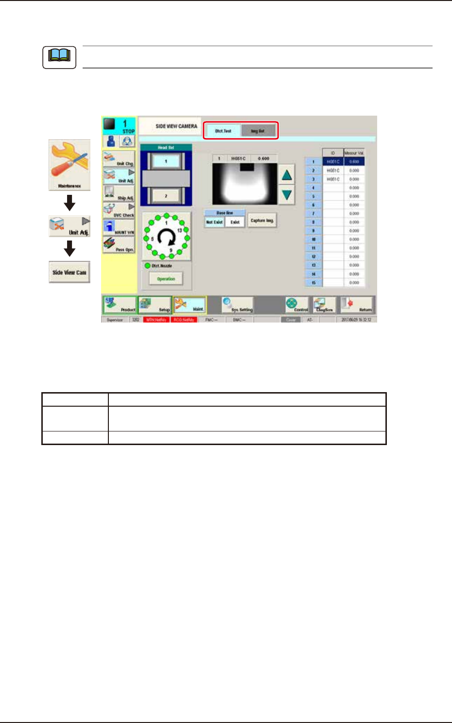
4.2 SIDE VIEW CAMERA
4.2 SIDE VIEW CAMERA
This window is not displayed when the multi-functional head is selected.
The nozzle detection test is performed with the side view camera attached to each placement head.
This window displays the measurement values and the captured images.
Graphic
Development
F3A15A
Tabs
The "SIDE VIEW CAMERA" window is provided with the following 2 tabs. When each tab is
pressed, the corresponding tab sheet appears.
Tab Description
Dtct. Test Performs the nozzle detection test for the specified head and shows
the results.
Img list Displays the imaged captured with the side view camera.
Note