EUKYX-199-3100_G5S2_Instruction_Vol3_E.pdf - 第81页
EUKYX 1-32 199-3100 5.5 PCB Recog Light 5.5 PCB Recog Light The wi ndow di spl ays the l igh t teach ing of PCB recogni tion camera. [1] [2] [3] Graphic Development F3A30 [ 1 ] T eaching Da ta Displa y Sec tion Dis pl a …
EUKYX
1-31199-3100
5.4 Cmp Recog Light
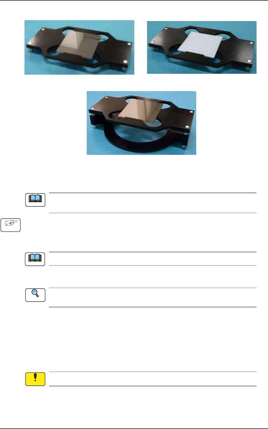
• Teaching Jig Set-up Diagram
Mirror Plane turned down and Tall Jig used
White Down Specular Down
F3A29
• Teaching Procedure
Before performing the teaching operation, press the [ZERO] button in the "Control" menu to
zero all axes.
(1) Select the component recognition camera for which the teaching is performed, in the
"Select Camera" section, and lighting pattern.
(2) Press the [XY Beam Save Pos] button and within 10 seconds, press the [START] button on
the operation panel.
The cover is unlocked automatically.
(3) Open the cover and set-up the teaching jig for the component recognition camera lighting
on the component recognition camera according to the lighting pattern.
Refer to "Teaching Jig Set-up Diagram" for the combination of the component recognition
lighting teaching jigs.
(4) Press the [JigSet Conf] button.
(5) Close the cover.
(6) Press the [Teach Start] button and within 10 seconds, press the [START] button on the
operation panel. (The corresponding window enables you to perform a teaching operation
on the lighting of the component recognition camera.)
(7) Press the [Cover Ready] button at the bottom of window and open the cover of relevant block.
(8) Remove the set-up component recognition lighting teaching jigs.
Unless the lighting teaching jigs are removed, the head would be damaged.
(9) Press the [JigDetach Conf] button.
(10) Press the [Save] button to save the teaching results.
(11) Close the cover.
Note
Procedure
Note
Reference
Notice
EUKYX
1-32199-3100
5.5 PCB Recog Light
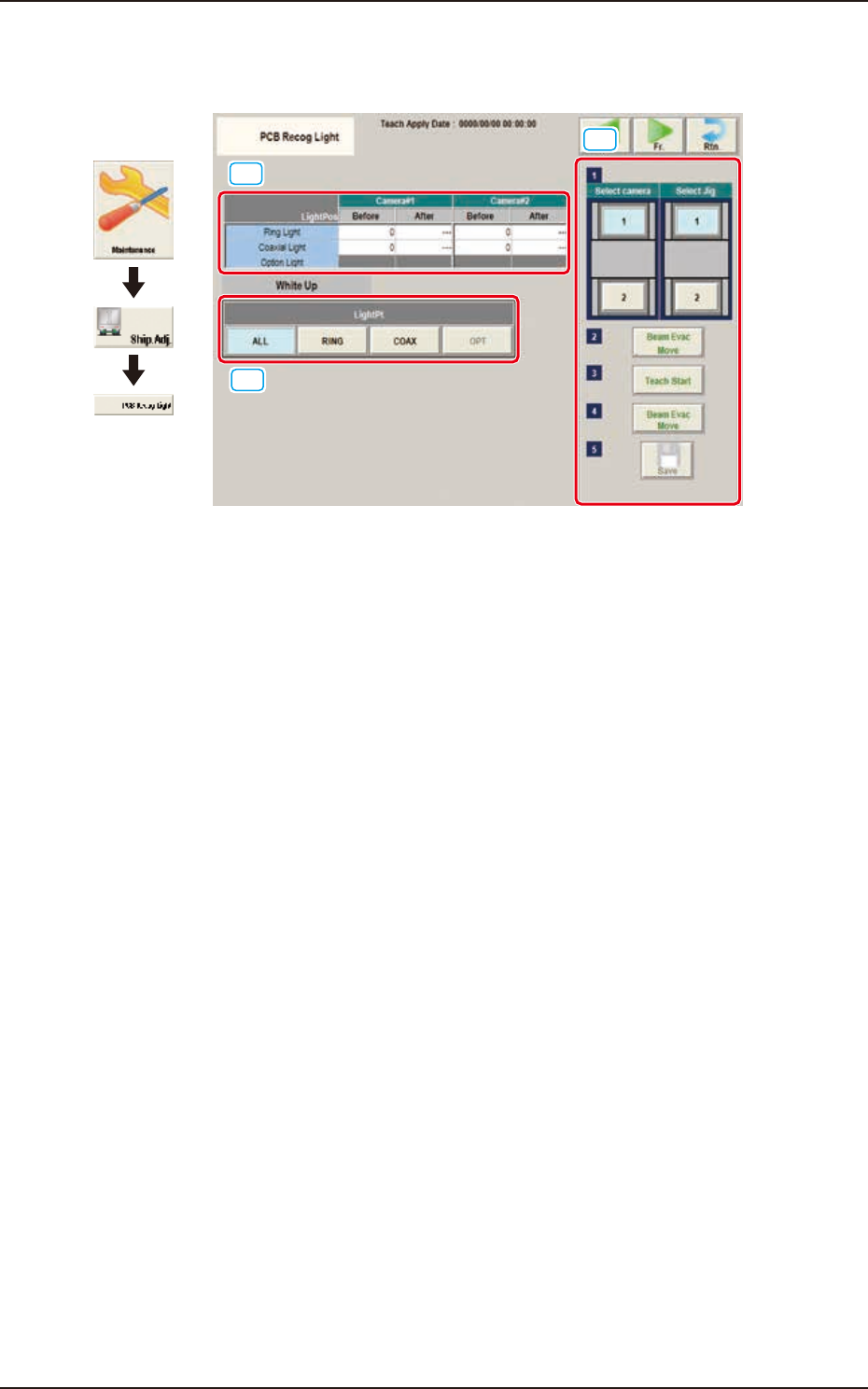
5.5 PCB Recog Light
The window displays the light teaching of PCB recognition camera.
[1]
[2]
[3]
Graphic
Development
F3A30
[1] Teaching Data Display Section
Displayed are offset data items for each lighting pattern for the designated camera.
[2] Teaching procedures section
The following buttons are arranged in teaching procedures section.
Select camera
Selects the PEC recognition camera to be taught.
Select Jig
Selects the block where the jig is set up.
[Beam Evac Move] button
Moves the XY beam to their home positions.
[Teach Start] button
Starts the teaching.
[Beam Evac Move] button
Moves the XY beam to their escape positions.
[Save] button
The teaching results are saved.
EUKYX
1-33199-3100
5.5 PCB Recog Light
[3] [Light Pt] button
The camera 1 or camera 2 lighting pattern is selected from the following items.
ALL : When selected, the teaching for the ring-lamp or coaxial lamp is performed.
RING : When selected, the teaching for the ring-lamp is performed.
COAX : When selected, the teaching for the coaxial lamp is performed.
• Teaching Jig for PEC Recognition Camera Lighting
The following jigs are used for the teaching on the PEC recognition camera lighting. Before the
teaching, combine the jig with the teaching glass jig mounting support jig and place it on the PEC
recognition camera. After the teaching operation, remove it.
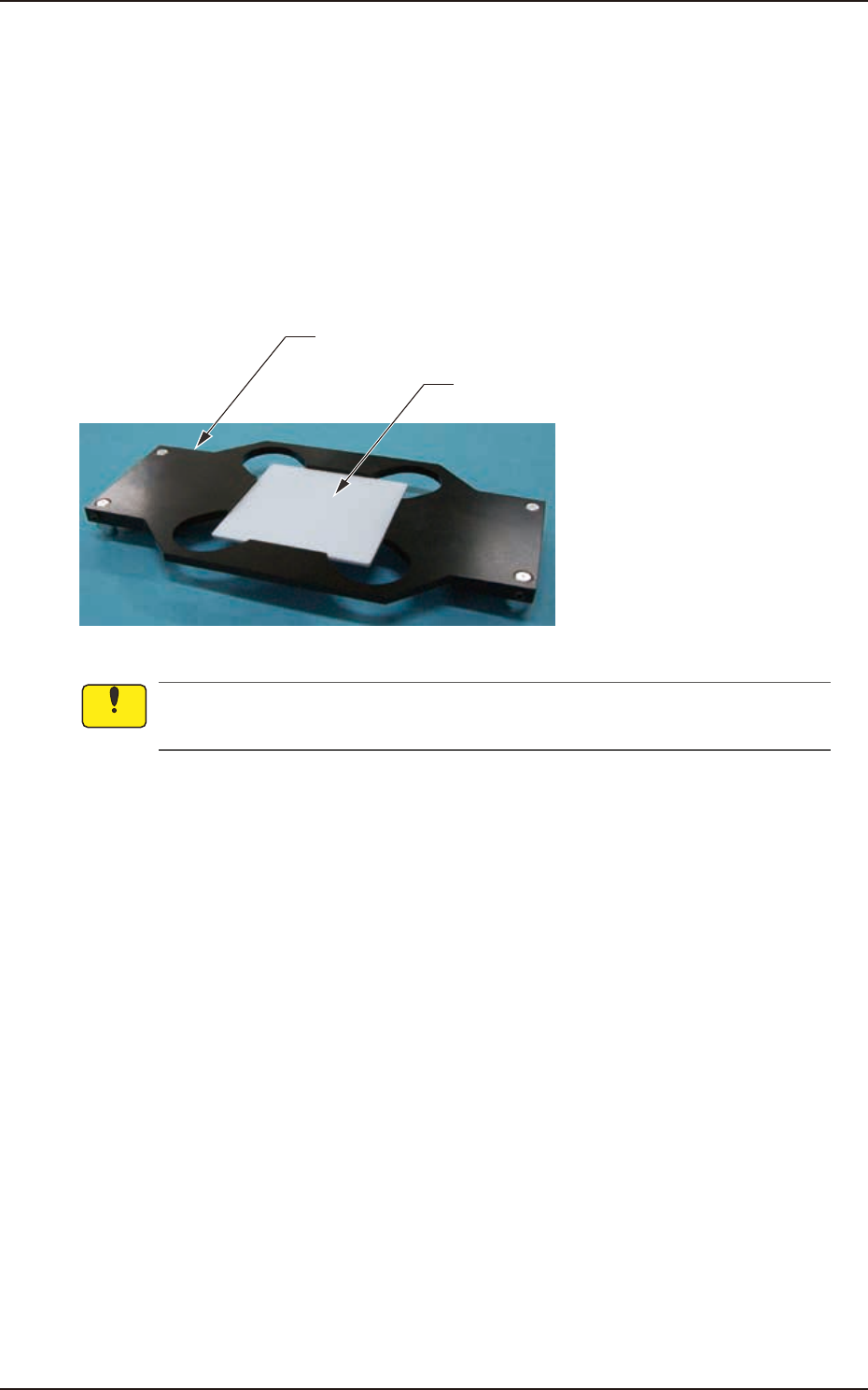
Teaching Glass Jig Mounting Support Jig
Teaching Glass Jig
(JG-0287,KYF-M8840-00)
(JG-0286,KYF-M8830-00)
F3A31
Set-up the teaching glass jig mounting support jig securely so that it does not rise. If the
mounting condition is not satisfactory, the head, etc., might be damaged.
Notice