EUKYX-199-3100_G5S2_Instruction_Vol3_E.pdf - 第180页
EUKYX 2-32 199-3100 2.5 Head [2] ON [sec] The specified parameter i s used to adj ust t he tim in g to turn the va cuu m on whi le the NL -a xis i s descending f or component pic k . When “ + 0.00 0” is specified i n the…
EUKYX
2-31199-3100
2.5 Head
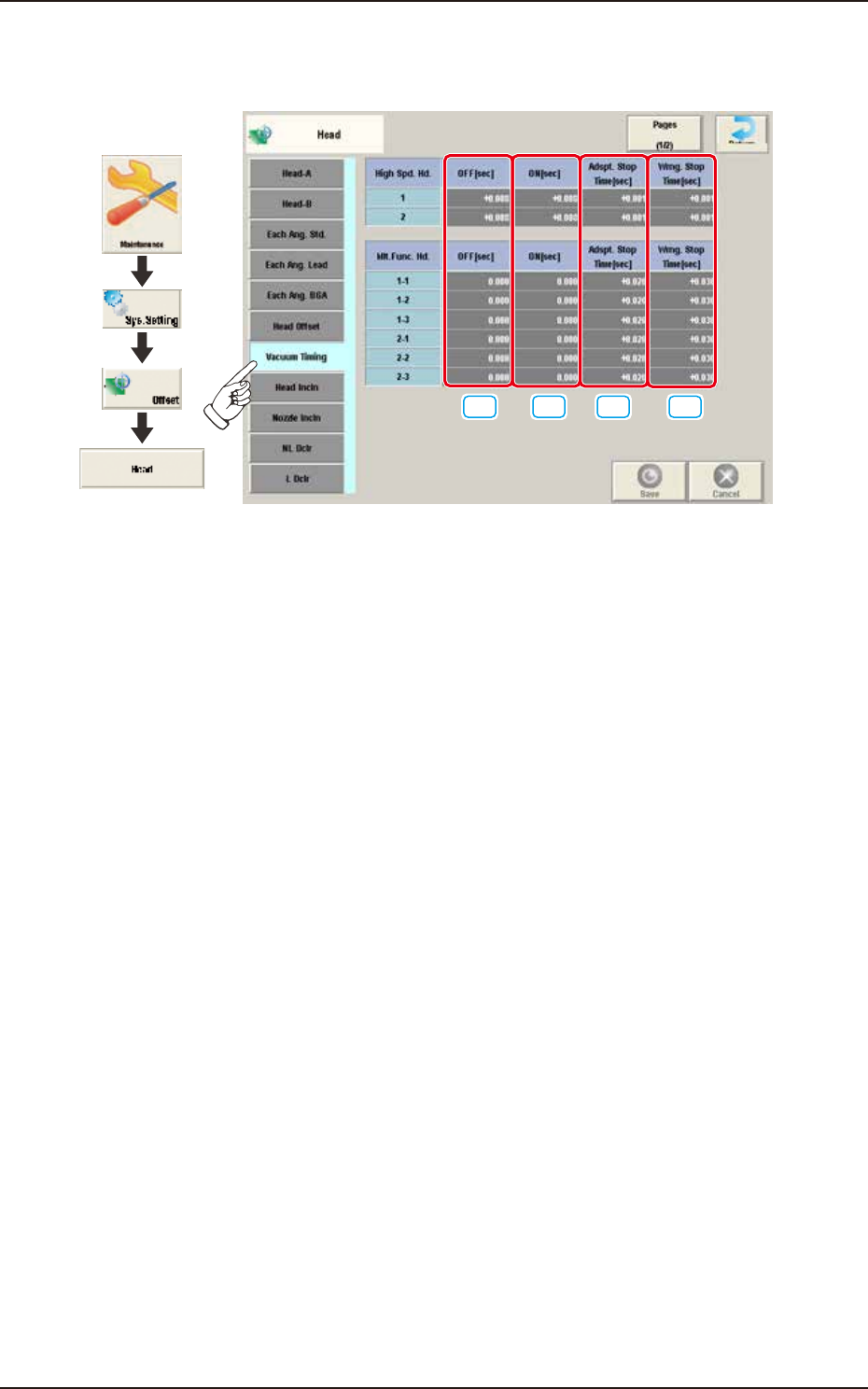
2.5.7 Vacuum Timing
Pressing the [Vacuum Timing] tab on the "Head" window displays the following window.
[1] [2] [3] [4]
Graphic
Development
F3B40A
[1] OFF [sec]
The specified parameter is used to adjust the timing to turn the vacuum off while the NL-axis is
descending for component placement.
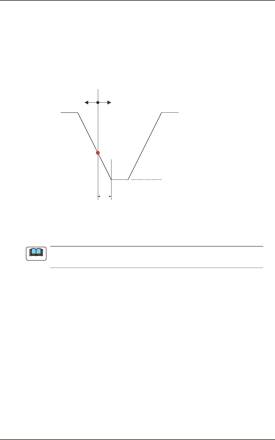
When "+0.000" is specified in the "OFF" text box, the vacuum is turned off when the NL-axis has
reached 10 ms away from the bottom arrival point.
Base on the point 10 ms away from the NL-axis bottom arrival point, a plus value in the "OFF" text
box means that the timing to turn off the vacuum will be delayed. A minus value means that the
timing will be quickened.
EUKYX
2-32199-3100
2.5 Head
[2] ON [sec]
The specified parameter is used to adjust the timing to turn the vacuum on while the NL-axis is
descending for component pick.
When “+0.000” is specified in the “ON” text box, the vacuum is turned on when the NL-axis has
reached 10 ms away from the bottom arrival point.
Base on the point 10 ms away from the NL-axis bottom arrival point, a plus value in the “ON” text
box means that the timing to turn on the vacuum will be delayed. A minus value means that the
timing will be quickened.
NL-Axis Bottom Arrival Point
NL-Axis Descending
10ms
(+)(-)
NL-Axis Ascending
Vacuum ON/OFF Timing Reference
F3B41
[3] Adspt. Stop Time [sec]
The parameter to specify the time when the nozzle must be stopped at the lower limit is set for al
component picks, in this data entry area.
This function is used when components cannot be picked up in stable condition due to the
influence of the component pick-up surface and the compatibility with the selected nozzle.
[4] Wrng. Stop Time [sec]
The parameter to specify the time when the nozzle must be stopped at the lower limit is set for the
placement of all components, in this data entry area.
Note
EUKYX
2-33199-3100
2.5 Head
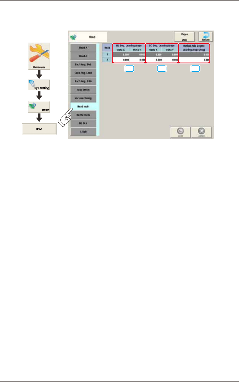
2.5.8 Head Incln
Pressing the [Head Incln] tab on the "Head" window displays the following window.
[1] [2] [3]
Graphic
Development
F3B42A
[1] HL Deg. Leaning Angle
theta X [deg], theta Y [deg]
The set parameter is used to correct the deviations in the X and Y direction that will be caused
while the HL-axis is moving down if the axis is tilted.
[2] DD Deg. Leaning Angle
theta X [deg], theta Y [deg]
The set parameter is used to correct the deviations in the X and Y direction that will be caused
while the HL-axis is moving down if the DD-axis is tilted.
[3] Optical Axis Degree Leaning Angle [Ang]
The set parameter is used to correct the angle of the component recognition camera shot.