EUKYX-199-3100_G5S2_Instruction_Vol3_E.pdf - 第62页
EUKYX 1-13 199-3100 4.1 NOZ. CHNG. [ 4] "Control Switch" Group Box The following operat ion but to ns are ar ranged. When the [ ST ART] but ton on the op erati on panel i s pre ssed withi n 1 0 seconds af ter t…
EUKYX
1-12199-3100
4.1 NOZ. CHNG.
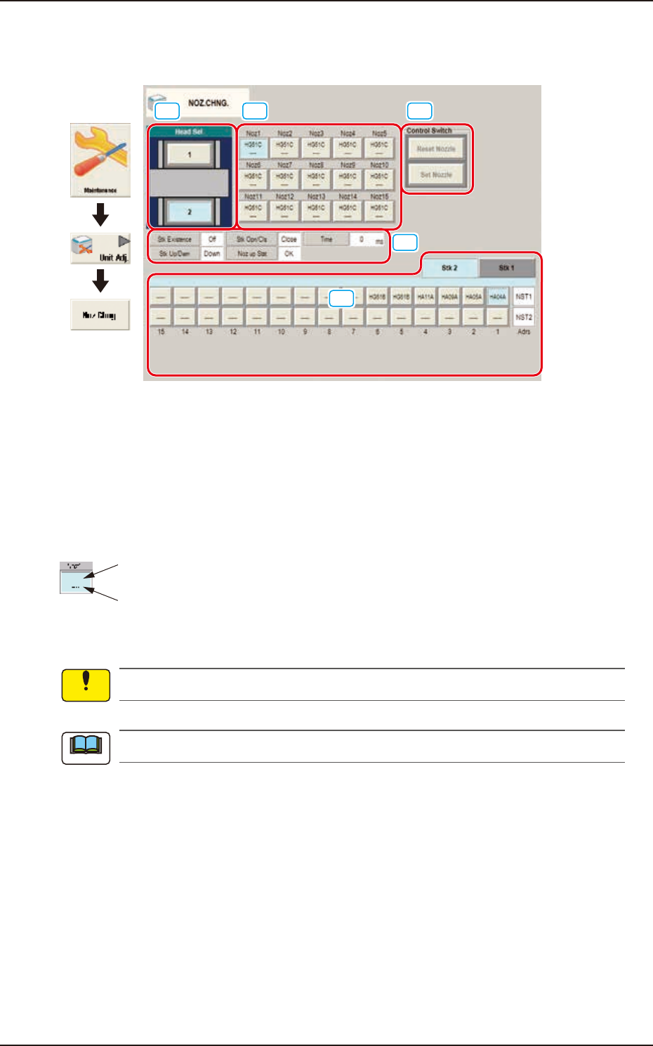
4.1 NOZ. CHNG.
The nozzle attachment and housing can be performed manually.
[1] [2] [4]
[5]
[3]
Graphic
Development
F3A14
[1] Head Sel
When a button is pressed, the corresponding head is selected as an object one for nozzle change
operation.
[2] Nozzle Allocation No. Selection Buttons
When a button is pressed, the corresponding nozzle to be changed is selected.
The background color of the button turns light blue.
ID of Attached Vacuum Nozzle
Nozzle Stocker Address
(Home Address for Attached Nozzle)
F3A18
No nozzles can be allocated to both sides of the middle-size odd shaped nozzle if attached.
The indications on the window vary depending on the selected head.
[3] Status Indication
Displayed is the condition of the currently selected head.
Notice
Note
EUKYX
1-13199-3100
4.1 NOZ. CHNG.
[4] "Control Switch" Group Box
The following operation buttons are arranged.
When the [START] button on the operation panel is pressed within 10 seconds after the each
operation button, the selected action takes place.
[Reset Nozzle] Button
When selected, this button stores the specified nozzle in the nozzle stocker.
When this button is pressed, the background color turns green, indicating that the head
selection button is set active.
[Set Nozzle] Button
When selected, this button picks up the selected nozzle from the nozzle stocker and
attaches it to the specified nozzle No. position.
When this button is pressed, the background color turns green, indicating that the head and
nozzle (nozzle stocker) selection buttons are set active.
[5] Nozzle Stocker tab
Using this tab, the nozzle stocker to be opened or closed and the nozzle housed in the nozzle
stocker, are designated.
Selecting the nozzle stocker using the nozzle stocker select tab and pressing the button for an
appropriate nozzle, designates the nozzle to be used.
For the stocker for which the skip has been set, a message is displayed and the stocker can not
be operated.
Note
EUKYX
1-14199-3100
4.1 NOZ. CHNG.
• Procedure for Nozzle Storage
(a) When the high-speed nozzle are used together with the middle-size odd shaped nozzle,
the middle-size odd shaped nozzle must be stored prior to the others.
When the machine starts to store the high-speed nozzle prior to the middle-size odd
shaped nozzle, a dialog box opens, prompting that the middle-size odd shaped nozzle
must be stored first and indicating that the high-speed nozzle cannot be stored.
(b) Do not house the nozzle while the head picks up a component. Doing so breaks the
vacuum and the component drops.
(1) Press the head (one of the head selection buttons) holding the nozzle desired to be stored.
(The background color of the selected button turns light blue.)
(2) Select the nozzle (one of the nozzle allocation No. selection buttons) holding the nozzle
desired to be stored.
(The background color of the selected button turns light blue.)
(3) To select a nozzle stocker different from the original one, press the nozzle selection button
(destination address).
(4) Press the [Reset Nozzle] button.
(The background color of the button turns green and the selected head selection button,
nozzle allocation No. button, and nozzle selection button are set active.)
(5) Press the [START] button on the operation panel.
(The selected nozzle will be housed in the nozzle stocker with the selected address.)
• Procedure for Nozzle Attachment
(a) The middle-size odd shaped nozzle can be attached, leaving one out of every two
pitches empty.
(b) When the high-speed nozzle are used together with the middle-size odd shaped nozzle,
the high-speed nozzle must be attached prior to the others.
When the machine starts to attach the middle-size odd shaped nozzle prior to the
high-speed nozzle, a dialog box opens, prompting that the high-speed nozzle must be
attached first and indicating that the middle-size odd shaped nozzle cannot be attached.
(c) Do not house the nozzle while the head picks up a component. Doing so breaks the
vacuum and the component drops.
(1) Select the head (one of the head selection buttons) where the desired nozzle should be
attached. (The background color of the selected button turns light blue.)
(2) Select the nozzle selection button where the nozzle to be attached is stored.
(The background color of the selected button turns light blue.)
(3) Select the nozzle allocation No. button to specify the position where the nozzle should be
attached. (The background color of the selected button turns light blue.)
(4) Press the [Set Nozzle] button.
(The background color of the button turns green and the selected head selection button,
nozzle allocation No. button, and nozzle selection button are set active.)
(5) Press the [START] button on the operation panel.
(The specified nozzle placement operation will be performed.)
No nozzle can be attached to any nozzle No. position where a nozzle is already attached.
Notice
Procedure
Notice
Procedure
Note