EUKYX-199-3100_G5S2_Instruction_Vol3_E.pdf - 第70页
EUKYX 1-21 199-3100 4.3 CONVEYOR [ 3] Convey or Set up But tons When the t arget positi on is mo ved, the con vey or width ad ju stment val ue s are setup usi ng the followi ng but tons. [T gt Wd ] But t on When this but…
EUKYX
1-20199-3100
4.3 CONVEYOR
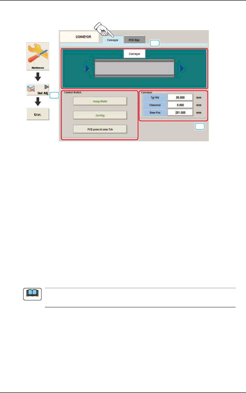
4.3.1 Conveyor
[1]
[2]
[3]
Graphic
Development
F3A20
[1] Conveyor Display Section
The conveyor image is displayed in this section.
[2] Control Switch
These buttons are arranged to perform the following setup operations. When any button is
selected, the background color of the selected button turns green.
[Desig Width] Button
When each value for "Tgt Wd", "Clearance" and "Base Pos" are set and the [START] button
on the operation panel is pressed within 10 seconds after pressing this button, the target
position movement is performed.
[Zeroing] Button
When the [START] button on the operation panel is pressed, within 10 seconds after pressing
this button, the conveyor zeroing operation is performed.
[PCB posn.lct.snsr.Tch] Button
When this button is pressed, the teaching operation for the PCB positioning detection sensor
is performed based on the current conveyor width.
When there is a PCB on the conveyor, accurate teaching is not available. Make sure that there
is no PCB on the conveyor and press this button to perform the teaching operation.
Note

EUKYX
1-21199-3100
4.3 CONVEYOR
[3] Conveyor Setup Buttons
When the target position is moved, the conveyor width adjustment values are setup using the
following buttons.
[Tgt Wd] Button
When this button is pressed, the "Tgt Wd" input window appears. When a value is entered
and the [SET] button is pressed, the target value is setup.
[Clearance] Button
When this button is pressed, the "Clearance" input window appears.
Set the data for the conveyor width to have some margin from the PCB size set in the pattern
program. The actual conveyor width is "PCB Size" (Target Width) + "Clearance"
(Recommended Value: 0.5 mm).
When a value is entered and the [SET] button is pressed, the clearance value is setup.
[Base Pos] Button
When this button is pressed, the "Base Pos" input window appears. In this window, the base
position adjusting data is setup. When the value is entered and the [SET] button is pressed,
the base position is setup.
■
Conveyor Width Manual Setup
When the conveyor width is set up, use the following procedure.
(1) In each input window displayed by pressing the [Tgt Wd], [Clearance] and [Base Pos]
buttons for the "Conveyor" width, enter the data parameter for each item.
(2) Within 10 seconds after pressing the [Tgt Wd] button, press the [START] button on the
operation panel. (The conveyor width will be adjusted to ("Tgt Wd" value + "Clearance"
value). Also, the conveyor will be moved to the set base position.)
Procedure
EUKYX
1-22199-3100
4.3 CONVEYOR
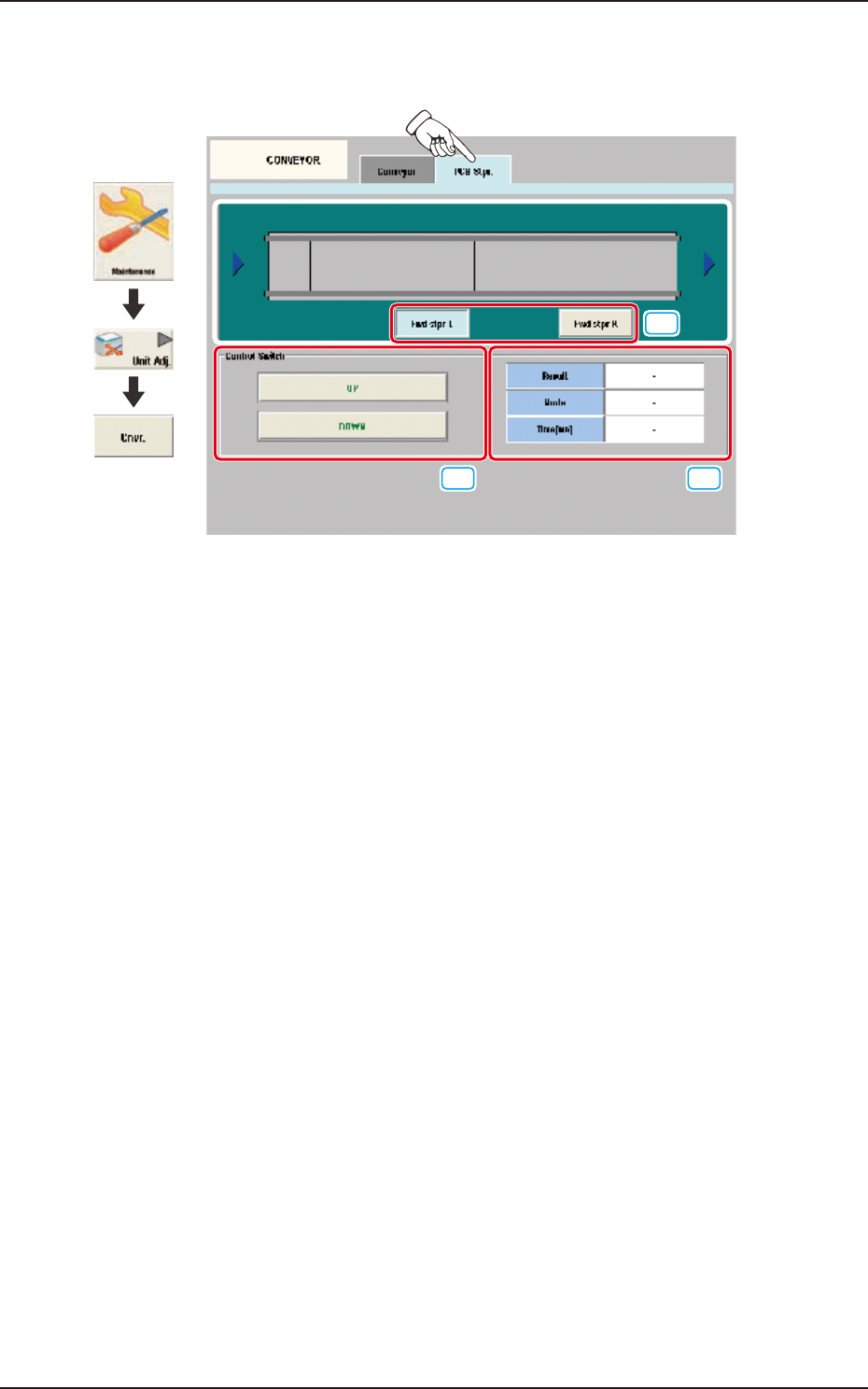
4.3.2 PCB Stpr.
The adjustment for each PCB stopper is performed on this tab sheet.
[1]
[2] [3]
Graphic
Development
F3A21
[1] PCB Stopper Selection Buttons
Select the PCB stopper to be operated.
[2] Control Switch
[UP] Button
When the [START] button is pressed on the operation panel within 10 seconds after this
button is pressed, the selected PCB stopper is moved up.
[DOWN] Button
When the [START] button is pressed on the operation panel within 10 seconds after this
button is pressed, the selected PCB stopper is moved down.
[3] Status Display
Result
In this data box the PCB stopper operation result is displayed as "OK" or "NG".
Mode
In this data box the PCB stopper present status is displayed as "UP" or "Down".
Time [ms]
In this data box the PCB stopper operation time is displayed.