EUKYX-199-3100_G5S2_Instruction_Vol3_E.pdf - 第96页
EUKYX 1-47 199-3100 5.1 1 Head Cntr Mark Pos • Hea d Rotational Ce nter O ff set Xm-Ym: Machine Reference Coordinate System Xm(+) Ym(+) Head Rotational Center PEC Recognition Camera Center Pm. Machine Reference Coordinat…
EUKYX
1-46199-3100
5.11 Head Cntr Mark Pos
[3] [Light Emitter Mark] tab
This tab appears when selecting the "Mark Pos".
This tab switches the "Light Emitter Mark recognition teaching" screen and "Mark Position teaching"
screen. When the "Light Emitter Mark recognition teaching" screen is selected, the tab color
changes to light blue.
• Teaching Jig
For the head rotational center offset/reference mark offset teachings, the QFP glass jig JG-0188
(KYB-M381P-00) is used.
• Jig Pick-up Nozzle
For the pick-up of the QFP glass jig, the jig nozzle (standard equipment) or normal vacuum nozzle
HV19C is used.
• Teaching Procedure
(1) Before the teaching operation, change the nozzle to the jig nozzle and setup the QFP glass
jig in the jig setup position over the component recognition camera.
(2) Select the head (1, 2 or All) for which the head rotational center offset / reference mark
offset teachings are performed.
In the case that the multi-functional head is selected in the "Select Head" section, select the
nozzle to be taught and press the [Teach Start] button.
(3) Press the [Teach Start] button on the "Head Cntr" tab sheet.
(The head rotational center offset teaching will be executed.)
• During this temporary stop mode, the selection of any other menu item is unavailable.
• When the offset teaching is completed, the designated head returns to the home position
automatically.
The teaching results are displayed in the "Head Cntr Teaching" Display Area.
(4) Press the [Teach Start] on the "Mark Pos" tab sheet.
(The reference mark offset teaching operation will be executed.)
• During this temporary stop mode, the selection of any other menu item is unavailable.
• When the offset teaching is completed, the designated head returns to the home position
automatically.
The teaching results are displayed in the "Mark Pos Teaching" Display Area.
(5) When the teaching operation is completed, remove the QFP glass jig.
(6) Press the [Save] button. (The teaching results are saved.)
Procedure
Note
Note
Note
EUKYX
1-47199-3100
5.11 Head Cntr Mark Pos
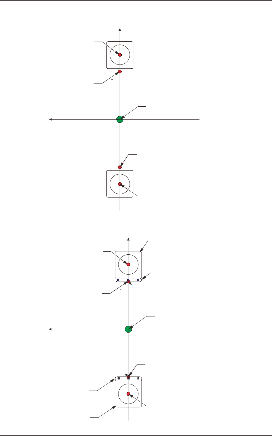
• Head Rotational Center Offset
Xm-Ym: Machine Reference
Coordinate System
Xm(+)
Ym(+)
Head Rotational Center
PEC Recognition
Camera Center
Pm. Machine Reference
Coordinate Origin
PEC Recognition
Camera Center
Head Rotational Center
F3A41
• Reference Mark Offset
Xm-Ym: Machine Reference
Coordinate System
Xm(+)
Ym(+)
Component Recognition
Camera
Head Rotational Center
Reference Mark
PEC Recognition
Camera Center
Pm. Machine Reference
Coordinate Origin
Reference Mark
PEC Recognition
Camera Center
Component
Recognition Camera
Head Rotational Center
F3A42
EUKYX
1-48199-3100
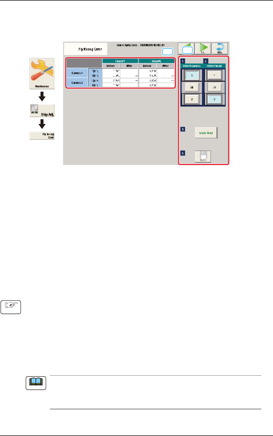
5.12 Fly Recog Camr
5.12 Fly Recog Camr
The set parameters are used to prevent a component from getting affected by the delay and staying
out of camera field of view.
[1]
[2]
Graphic
Development
F3A43
[1] Teaching Data Display Section
Displayed are the offset data items for the designated camera.
[2] Teaching procedures section
The following buttons are arranged in teaching procedures section.
Select camera
Selects the camera to be taught.
Select head
Selects the head to be taught.
[Teach Start] button
Starts the teaching.
[Save] button
The teaching results are saved.
• Teaching Procedure
(1) Select the Camera and Head (1, 2 or All) for which the teaching is performed.
(2) Press the [Teach Start] button.
(Move the PEC recognition mark onto the reference mark on the side of the component
recognition camera lighting and recognize the reference mark while the camera is in the
stop mode. (At that time, the beam position is regarded as (X, Y).)
Fix the beam X onto the coordinate X and move the beam Y at the constant speed (2 m/s).
Then, when the PEC recognition camera passes over the reference mark, perform the fly
image shooting to recognize the mark.
The difference from the data obtained when the camera is stopped, is regarded as the fly
recognition offset.
During this temporary stop mode, the selection of any other menu item is unavailable. When
the offset teaching is completed, the designated head returns to the home position
automatically. The teaching results are displayed in the “Fly Recog Camr Offset Teaching”
Display Area.
(3) Press the [Save] button. (The teaching results are saved.)
Procedure
Note