PathMaster-REV-L-4.5-1.pdf - 第101页
Machine Operati on Manual Revision L / February 2020 Page 101 of 200 FastArea™ FastArea™ is faster tha n the stan dard area beca use it preve nts tool c ycling betw een row s. This feature c an grea tly d ecrease cy cle …
Machine Operation Manual
Revision L /
February 2020
Page 100 of 200
NOTE: Playback can only be operated if the workcell is currently in Manual mode. Only three
points are required for the Area tool.
How the Area Function Works
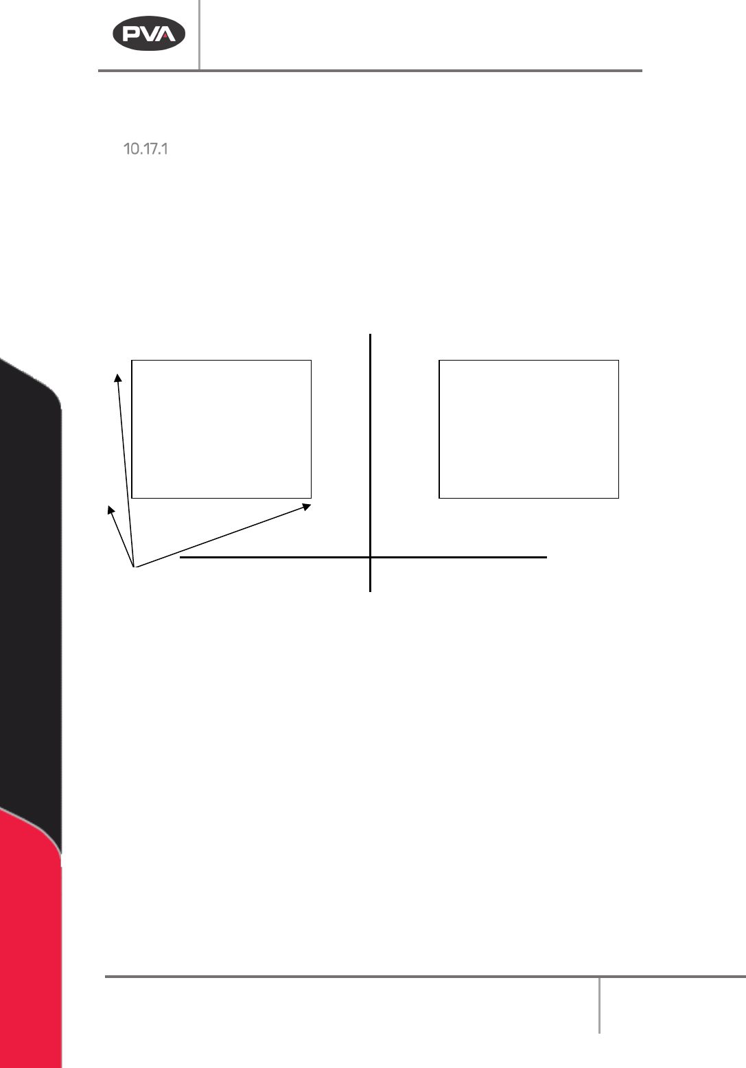
Area path segments are calculated with three points as shown below:
Point 1 defines the start of the pattern. Point 2 defines the direction and length of the
pattern. After the direction of the pattern is determined, the distance from point 1 to point
3 determines the width of the pattern.
The width is divided by the ‘Area Spacing’ (or ‘Path Spacing’) parameter on the Area
function screen. The value given is the number of passes needed to fill the given area.
Area #1 Area #2
Area #1
• Point 1 defines the start.
• Point 2 is along the X-axis, so that is the direction of the path. The length of the
path is the distance over the X-axis. Therefore, the width is along the Y-axis.
• Point 3 defines the width. The width is the difference in Y between points 1 and 3.
This is divided by the ‘Area Spacing’ (or ‘Path Spacing’) parameter resulting in the
number of paths the machine needs to run to fill the given area.
Area #2
• Point 1 defines the start.
• Point 2 is along the Y-axis, so that is the direction of the path. The length of the
path is the distance over the Y-axis. Therefore, the width is along the Y-axis.
• Point 3 defines the width. The width is the difference in X between points 1 and 3.
This is divided by the ‘Area Spacing’ (or ‘Path Spacing’) parameter resulting in the
number of paths the machine needs to run to fill the given area.
Point
1
1
2
2
3
3
X
Y
Machine Operation Manual
Revision L /
February 2020
Page 101 of 200
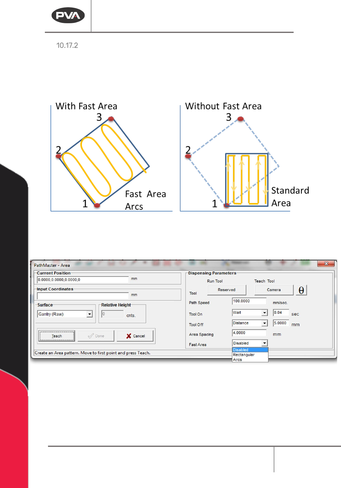
FastArea™
FastArea™ is faster than the standard area because it prevents tool cycling between rows.
This feature can greatly decrease cycle time. The way coordinates are taught with
FastArea
TM
is different than a normal area. Each point defines the 3 corners of the
rectangle, and the path will fit into area. Refer to the figure below.
Figure 118: Fast Area
1. To use the FastArea™ feature teach a standard area. Refer to Section 10.17.
2. Select the type of fast area to be used (Disabled, Rectangular, Arcs).
Figure 119: Fast Area
3. Select “Done” to save the changes, or “Cancel” to exit and not save changes.
4. To edit a FastArea, double click on the path and change the command in the edit
window. Refer to Section 7.5.
Machine Operation Manual
Revision L /
February 2020
Page 102 of 200
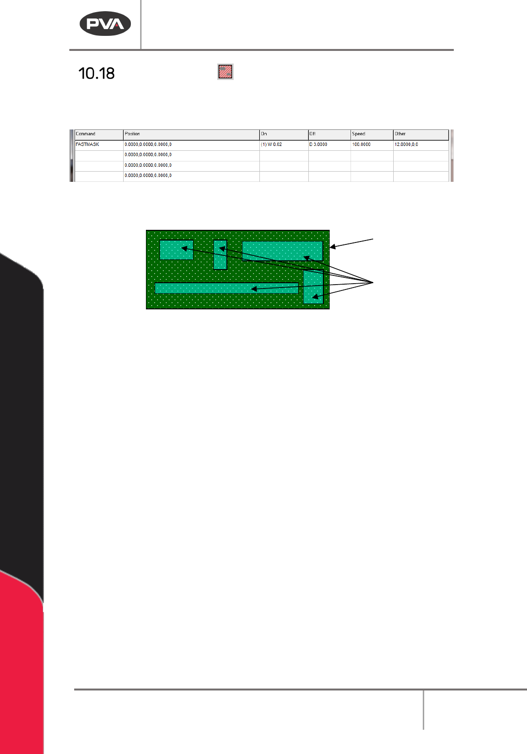
FastMask™
The FastMask™ function will create an area to be coated and keep outs within that area.
There can be up to 99 keep out areas specified within the coating area.
Figure 120: Programmed FastMask Command
Shown below is an example of a PCB (Printed Circuit Board) with keep out areas specified.
Figure 121: Sample Board with Keep out Areas
1. Select the FastMask™ function to open the wizard.
2. Select the Run Tool. Select (double click) the necessary tool from the Tool Selection
window. Refer to
Figure 68.
3. Select the Teach Tool if necessary. Select (double click) the necessary tool from the
Tool Selection window. Refer to
Figure 68.
4. Select “θ” to move the selected tool to the calibrated W-axis position (theta).
NOTE: The “θ” button will only be available on 4-axis machines. When you use the “Teach
Tool” (virtual tool 0) it is not necessary to select this button.
5. Set the Tool Height to “Use the Current Z Height” or “Use Calibrated Z Height”.
6. Set the Tool On to “Wait” or “Distance” and set the time or distance in the box.
7. Set the Tool Off to “Wait” or “Distance” and set the time or distance in the box.
8. Set the Path Speed.
9. Set the Area Spacing.
10. Select the appropriate tool parameters.
11. Teach two opposite corners of the area to be coated as point 1 and point 2.
Sample
Keep outs