PathMaster-REV-L-4.5-1.pdf - 第109页
Machine Operati on Manual Revision L / February 2020 Page 109 of 200 R un Se lection / Sequ ence The Run Sele ction fu nctio n will play back the sel ected path seg ment s in Wet, Dry or Camera mo de. Run Seq uence alway…
Machine Operation Manual
Revision L /
February 2020
Page 108 of 200
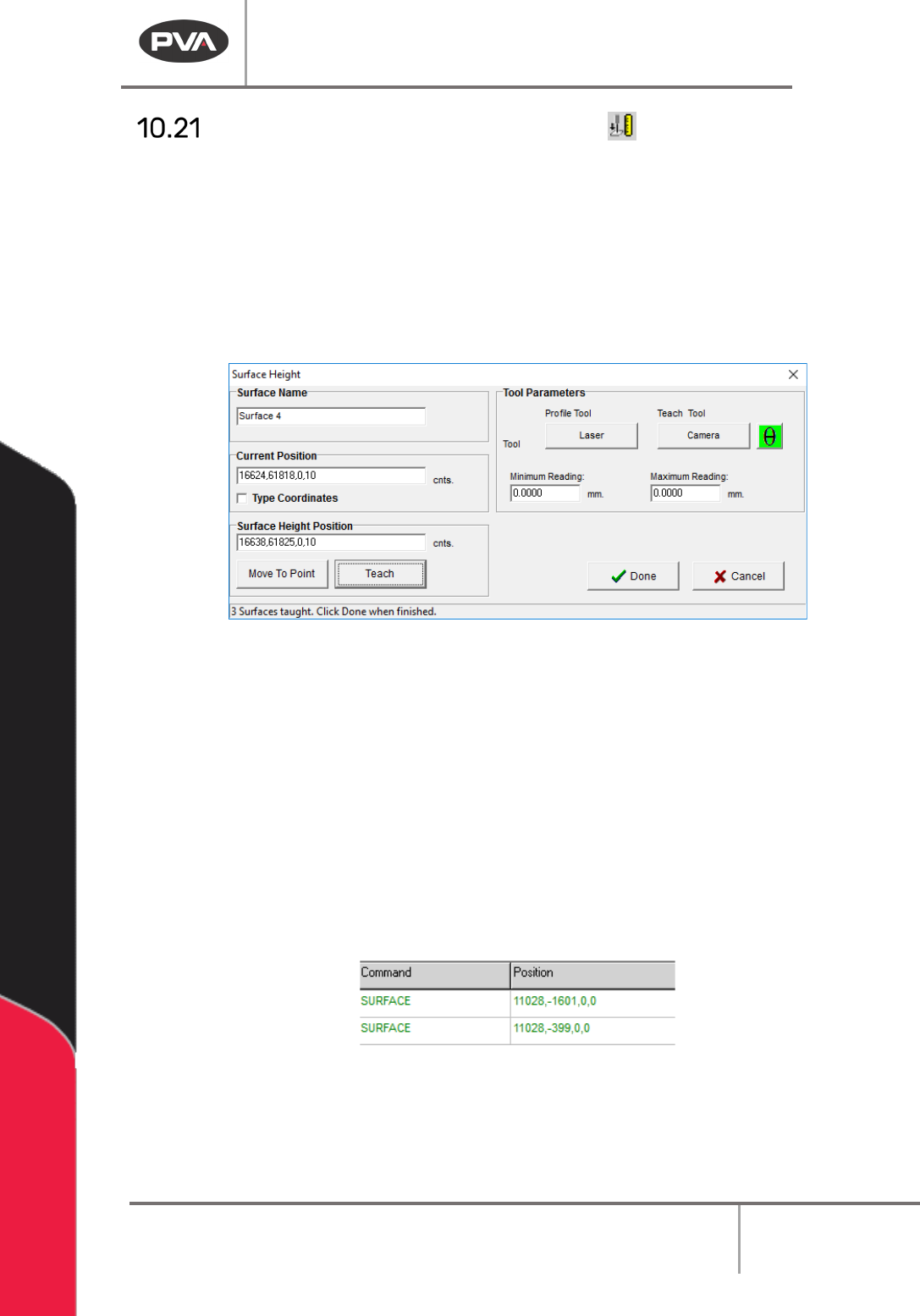
Surface Height (DMC 4000)
The Surface Height command is used to teach surfaces used in PolyLines. The surfaces
should be run in order, to count the different surfaces before the related paths are run. The
process is similar to fiducials.
1. Click on the surface height icon in the Programming Toolbar to open the surface
height interface.
2. Use the tool parameters subsection to find the necessary profile tool and teach tool
to teach surfaces for the current product.
Figure 130: Surface Height Teach Interface
3. If necessary, set a min/max for each surface height in the surface height teach
interface (in the tool parameters window). With these values, the machine can make
sure a part is within a set tolerance for a surface height reading. This reading can be
seen in the Portal front panel.
NOTE: After a Surface Height call, if the Profile Tool selected is on the head on a Z-Slide,
the user must program the necessary Tool Command to retract the Z-Slide.
NOTE: In Autocycle, if a part fails a surface height you can try again.
4. The Surface Name can be changed to any unique name on a per-program basis.
5. If necessary, use the Theta button to rotate the W-axis to the correct position.
Figure 131: Surface Command in Path Program
6. Click “Teach” to set the Surface Height Position for the height check.
7. Click “Done” to save the point and return to the main PathMaster® screen.
8. Repeat the Procedure to teach as many Surface Height Checks as necessary.
Machine Operation Manual
Revision L /
February 2020
Page 109 of 200
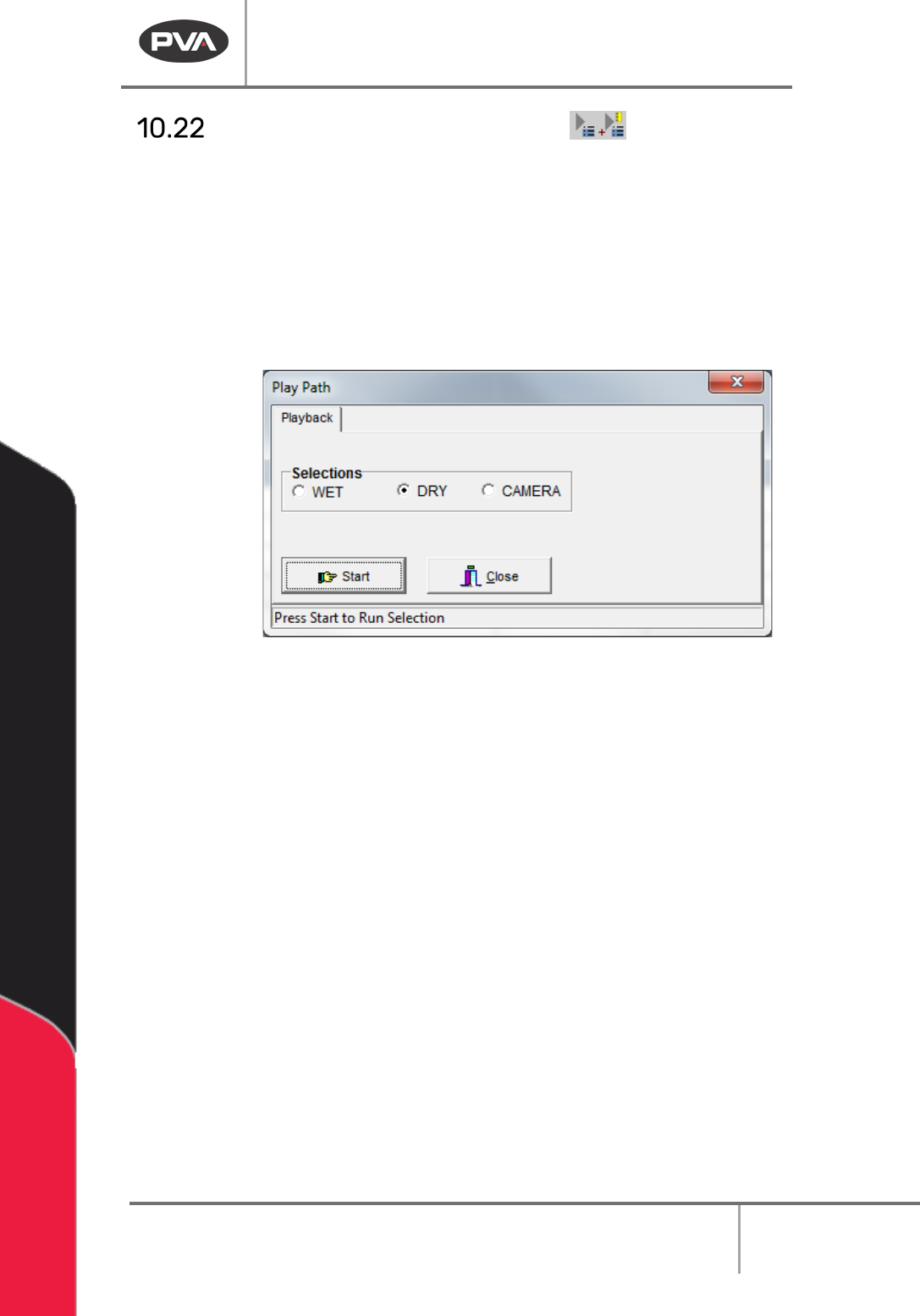
Run Selection / Sequence
The Run Selection function will play back the selected path segments in Wet, Dry or
Camera mode. Run Sequence always plays the entirety of the Path Program.
1. Select one or more commands.
2. Select the Run Selection function to play the highlighted commands or Run
Sequence to play all of the current Path Program.
6. Select “Wet”, “Dry”, or “Virtual Tool 0”. The name for the third option will be the
name of Virtual Tool 0.
Figure 132: Playback
3. Select “Start” to play the highlighted commands.
4. Select “Close” to exit and not play the path.
Machine Operation Manual
Revision L /
February 2020
Page 110 of 200
Z-Axis Height
NOTE: The “Use Current Z Height” and “Use Calibrated Z Height” checkboxes are only
shown when the Teach Tool is enabled. The Tool Offset table and Tool Parameters must be
correctly configured before use.
The teach tool can be used to make paths on the workcell. After a path segment is taught
with the teach tool, the tool can be changed to any other tool and the offset is set by
PathMaster.
The Z-axis (height) position is set by the user when path segments are taught, the teach
tool’s current Z-coordinate or a pre-calculated value, called the Calibrated Tool Height, can
be used. If the calibrated tool height is used, it will not be necessary to change the path
after it is complete, and when tool changes or needle calibrations are done, the offsets are
update for the path programs.
Tool Offset Height: The distance traveled by a specific tool from the Z-axis home position
to the workpiece.
Relative Height: The Z distance from the position taught as the tool offset reference
position on the calibration plate that the tool will operate at, set in the Tool Configuration
window. Also called
Gantry (Relative) in the Surface menu. Not available for 2D Line, 3D
Line, Area, Arc, Circle, Dot, Dot Array, Rectangular Spiral, and Spiral. Functions slightly
differently when used in the Move command.
Calibrated Z Height: The difference between a tool offset and the tool’s Relative Height is
the Calibrated Z Height for a tool. Also called
Calibrated Z, in the Surface menu.
Calibrated Z Height = Tool Offset Height – Relative Height
Additional Options in the Surface Menu:
Gantry (Raw) uses the Z coordinate exactly as it was taught.
Use Last uses the Z height of the previous Surface used in the Polyline. Not available for 2D
Line, 3D Line, Area, Arc, Circle, Dot, Dot Array, Rectangular Spiral, Spiral, and Move.
Custom Surface uses the XY coordinates of the Surface command that shares the same
name and uses the Z height and the current run tool’s “
Calibrated Z” to set the dispense Z
height.
NOTE: The available Z-height options depend on the workcell configuration and the
function being used.