PathMaster-REV-L-4.5-1.pdf - 第93页
Machine Operati on Manual Revision L / February 2020 Page 93 of 200 Arc This function teache s an a rc. An arc mus t have three points. The Z - axi s does no t change its positio n in the pat h. Refer to Sectio n 10.1 fo…

Machine Operation Manual
Revision L /
February 2020
Page 92 of 200
From Selected Line
8. To create a polyline from individual path segments, select the path segments to
include in the Polyline.
9. Select the Teach menu.
10. Select
Polyline -> From Selected Lines
.
If the endpoints of the path segments do not match up, PathMaster® will ask to match up
the endpoints and the polyline will use the best fit. If you do not to match up the endpoints
the polyline will not be made. Refer to Figure 101.
The tool used for the first segment and the θ
(Theta) position, will be used for the 3D
Polyline command. This function is helpful when dispensing gaskets and odd shaped
adhesive patterns where it is necessary to change height but have a continuous flow of
material.
11. To edit a polyline, double click on the path and change the commands in the edit
window. Refer to Section 7.5.
Machine Operation Manual
Revision L /
February 2020
Page 93 of 200
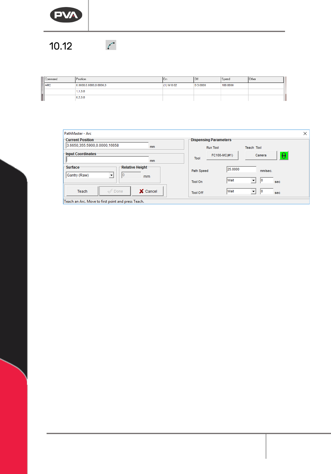
Arc
This function teaches an arc. An arc must have three points. The Z-axis does not change
its position in the path. Refer to Section 10.1 for definitions of the tool functions.
Figure 104: Programmed Arc Command
1. Select the Arc function.
Figure 105: Teach Arc
2. Select the Run Tool. Select (double click) the necessary tool from the Tool Selection
window. Refer to
Figure 68.
3. Select the Teach Tool if necessary. Select (double click) the necessary tool from the
Tool Selection window. Refer to
Figure 68.
4. Select “θ” to move the selected tool to the calibrated W-axis position (theta).
NOTE: The “θ” button will only be available on 4-axis machines. When you use the “Teach
Tool” (virtual tool 0) it is not necessary to select this button.
5. Select the Surface from the drop-down menu. In some units, you can set the
Relative Height.
6. Set the Path Speed.
7. Set the Tool On to “Wait” or “Distance” and set the time or distance in the box.
8. Set the Tool Off to “Wait” or “Distance” and set the time or distance in the box.
9. Teach the three points. Include the start point and move (clockwise or counter-
clockwise) in the direction the axes must move. Use the teach pendant or input the
coordinates.
NOTE: When you select points, space them evenly around the arc.
10. Select “Done” to save the changes, or “Cancel” to exit and not save changes.
11. To edit an Arc, double click on the path and change the command in the edit
window. Refer to Section 7.5.
Machine Operation Manual
Revision L /
February 2020
Page 94 of 200
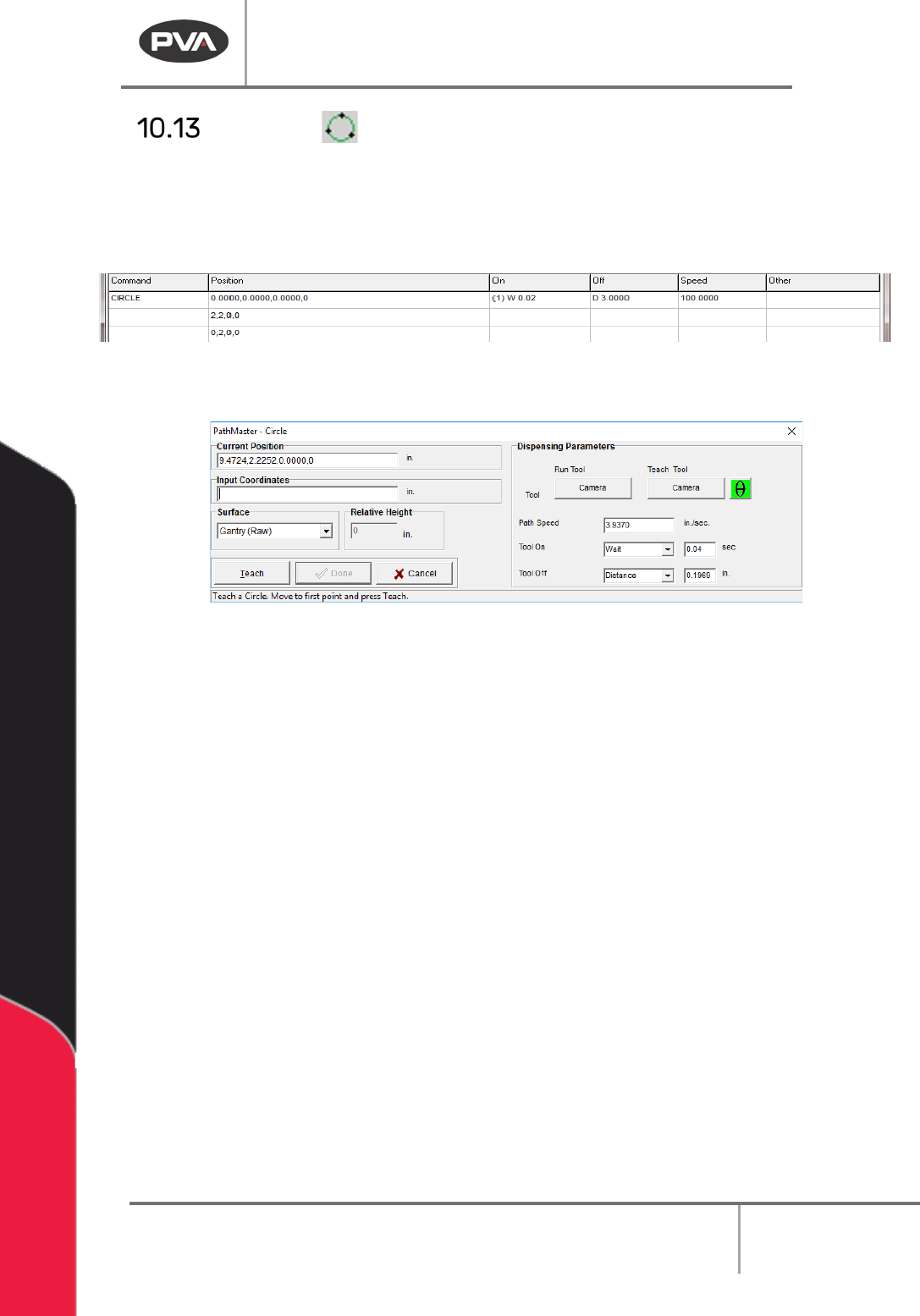
Circle
This function teaches a circle. A circle must have three points. The Z-axis does not change
position in this path. Refer to Section 10.1 for definitions of the tool functions.
NOTE: When you select points, space them evenly around the circle. Do not use the same
point for the first and last point.
Figure 106: Programmed Circle Command
1. Select the Circle function.
Figure 107: Teach Circle
2. Select the Run Tool. Select (double click) the necessary tool from the Tool Selection
window. Refer to
Figure 68.
3. Select the Teach Tool if necessary. Select (double click) the necessary tool from the
Tool Selection window. Refer to
Figure 68.
4. Select “θ” to move the selected tool to the calibrated W-axis position (theta).
NOTE: The “θ” button will only be available on 4-axis machines. When you use the “Teach
Tool” (virtual tool 0) it is not necessary to select this button.
5. Select the Surface from the drop-down menu. In some units, you can set the
Relative Height.
6. Set the Path Speed.
7. Set the Tool On to “Wait” or “Distance” and set the time or distance in the box.
8. Set the Tool Off to “Wait” or “Distance” and set the time or distance in the box.
9. Select three points on the circumference of the circle. Include the start point and
move (clockwise or counter-clockwise) in the direction the axes must move.
10. Select “Done” to save the changes, or “Cancel” to exit and not save changes.
11. To edit a circle, double click on the path and change the command in the edit
window. Refer to Section 7.5.
NOTE: You can only operate Playback if the workcell is in Manual mode.