PathMaster-REV-L-4.5-1.pdf - 第134页
Machine Operati on Manual Revision L / February 2020 Page 134 of 2 00 Required Element Description BEG IN1, BEGIN 2, et c. Define s t he st art of t he s egm ent. The t ool will tur n O N at this point. END1, END 2, etc.…
Machine Operation Manual
Revision L /
February 2020
Page 133 of 200
How to Import and Export Files
The PathMaster® can import and export programs, projects, and subroutines. It can also
import CAD files.
CAD Files
A 2-dimensional CAD drawing can be imported into PathMaster® as a path program.
There are several steps required for a successful import. These include:
• Create the path drawing in CAD.
• Add the PathMaster® codes to the CAD drawing.
• Turn the CAD drawing to the correct position as it relates to the workcell gantry.
• Export the CAD drawing to a *.dxf (Autodesk Drawing Exchange Format).
• Import the CAD drawing into PathMaster® with the CAD wizard.
• Prepare the CAD File.
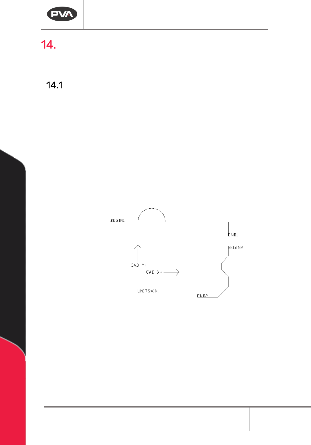
NOTE: The CAD X+ and CAD Y+ arrows are for reference only and are not necessary.
Figure 165: Original CAD Image
1. The start and end of each segment must be labeled as shown in the image above
and as described in the table below.
2. Put the units in the CAD drawing as shown.
Machine Operation Manual
Revision L /
February 2020
Page 134 of 200
Required Element
Description
BEGIN1, BEGIN2, etc.
Defines the start of the segment. The tool will turn ON at this
point.
END1, END2, etc.
Defines the end of the segment. The tool will turn OFF at this
point.
UNITS=IN.
UNITS=MM.
UNITS=CNTS.
Defines the units used for creating the drawing.
NOTE: The path will be converted automatically to the units specified in PathMaster® when
it is imported.
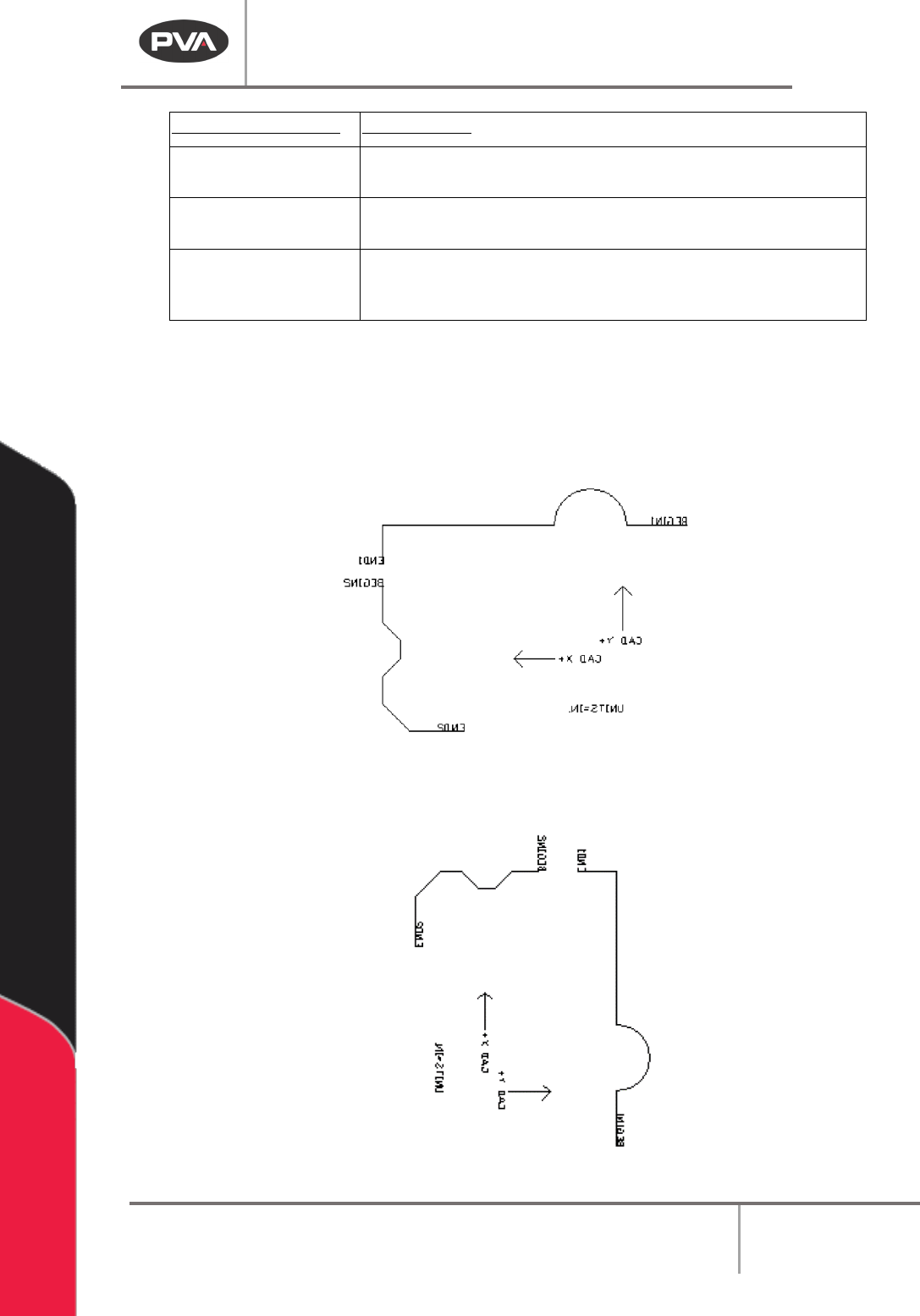
3. After all necessary elements have been put in the drawing it must be mirrored on
the Y axis.
NOTE: In AutoCAD be sure to “Delete Old Objects” when prompted.
Figure 166: CAD Drawing Mirrored on the Y Axis
4. Rotate the drawing clockwise 90° (-90° for standard AutoCAD Setup).
Figure 167: Rotate the CAD Drawing 90°
Machine Operation Manual
Revision L /
February 2020
Page 135 of 200
The final step is to export the file to a *.dxf.
5. In AutoCAD select the
File->Export
menu.
6. When the Export Data window comes up, select “Save As” Type AutoCAD
R12/LT2DXF.
7. Under the Options button make sure that the Export Format is ASCII.
8. Give the file a name and save it.
How to Import a DXF file into PathMaster
The path will be imported to a new program.
1. Select
File ->Import ->Program ->DXF File
from the main menu.
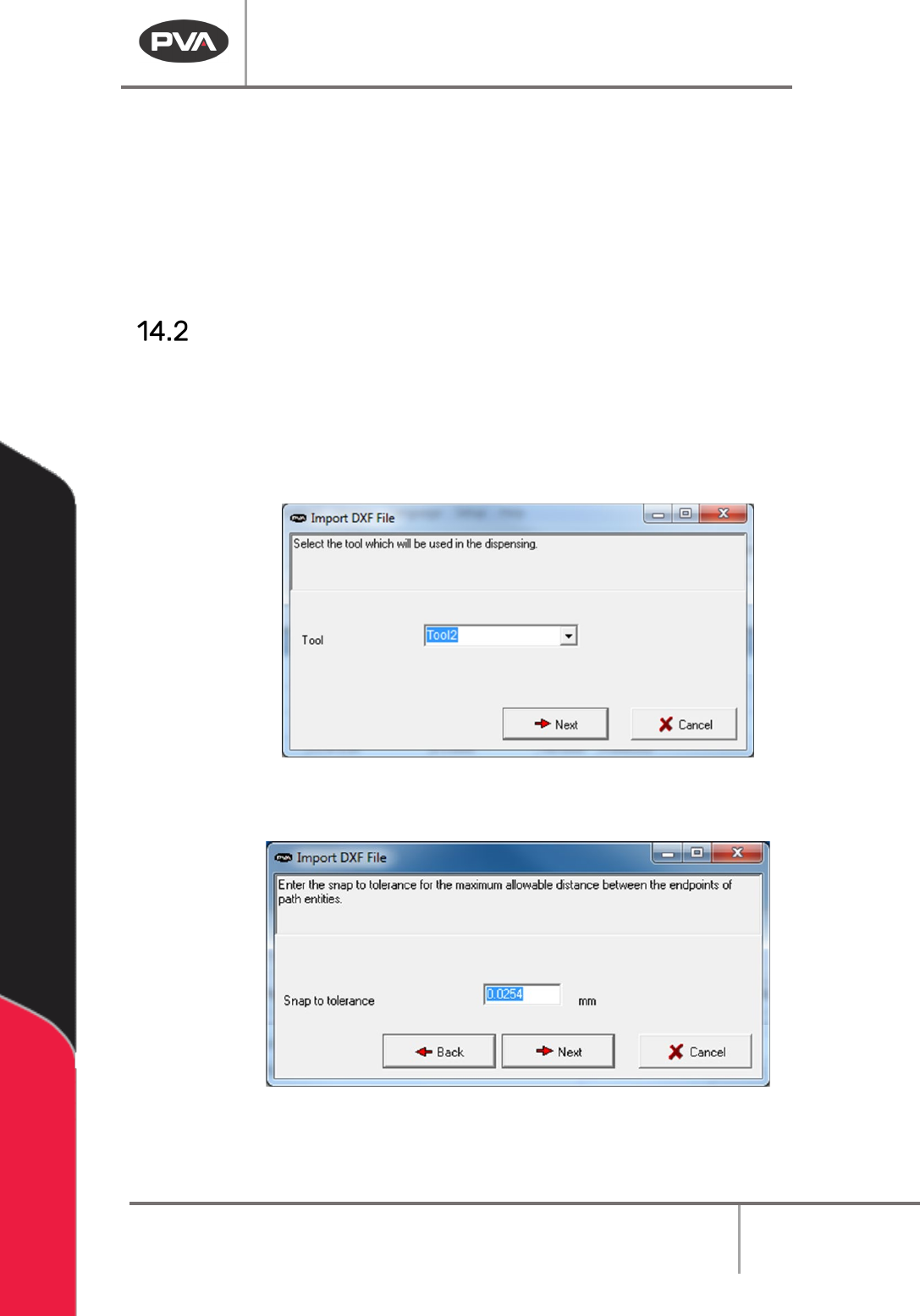
2. Select the Tool that will be used with the imported CAD file.
3. Select the “Next” button.
Figure 168: Select the Tool
4. Set the Snap to tolerance.
Figure 169: Set the Tolerance