PathMaster-REV-L-4.5-1.pdf - 第111页
Machine Operati on Manual Revision L / February 2020 Page 111 of 20 0 O ffset Details The offset hei ght is sho wn in PathM aste r’s Tool Configurati on window and set in the Camera Off set Trai ning windo w. Refer to Se…
Machine Operation Manual
Revision L /
February 2020
Page 110 of 200
Z-Axis Height
NOTE: The “Use Current Z Height” and “Use Calibrated Z Height” checkboxes are only
shown when the Teach Tool is enabled. The Tool Offset table and Tool Parameters must be
correctly configured before use.
The teach tool can be used to make paths on the workcell. After a path segment is taught
with the teach tool, the tool can be changed to any other tool and the offset is set by
PathMaster.
The Z-axis (height) position is set by the user when path segments are taught, the teach
tool’s current Z-coordinate or a pre-calculated value, called the Calibrated Tool Height, can
be used. If the calibrated tool height is used, it will not be necessary to change the path
after it is complete, and when tool changes or needle calibrations are done, the offsets are
update for the path programs.
Tool Offset Height: The distance traveled by a specific tool from the Z-axis home position
to the workpiece.
Relative Height: The Z distance from the position taught as the tool offset reference
position on the calibration plate that the tool will operate at, set in the Tool Configuration
window. Also called
Gantry (Relative) in the Surface menu. Not available for 2D Line, 3D
Line, Area, Arc, Circle, Dot, Dot Array, Rectangular Spiral, and Spiral. Functions slightly
differently when used in the Move command.
Calibrated Z Height: The difference between a tool offset and the tool’s Relative Height is
the Calibrated Z Height for a tool. Also called
Calibrated Z, in the Surface menu.
Calibrated Z Height = Tool Offset Height – Relative Height
Additional Options in the Surface Menu:
Gantry (Raw) uses the Z coordinate exactly as it was taught.
Use Last uses the Z height of the previous Surface used in the Polyline. Not available for 2D
Line, 3D Line, Area, Arc, Circle, Dot, Dot Array, Rectangular Spiral, Spiral, and Move.
Custom Surface uses the XY coordinates of the Surface command that shares the same
name and uses the Z height and the current run tool’s “
Calibrated Z” to set the dispense Z
height.
NOTE: The available Z-height options depend on the workcell configuration and the
function being used.
Machine Operation Manual
Revision L /
February 2020
Page 111 of 200
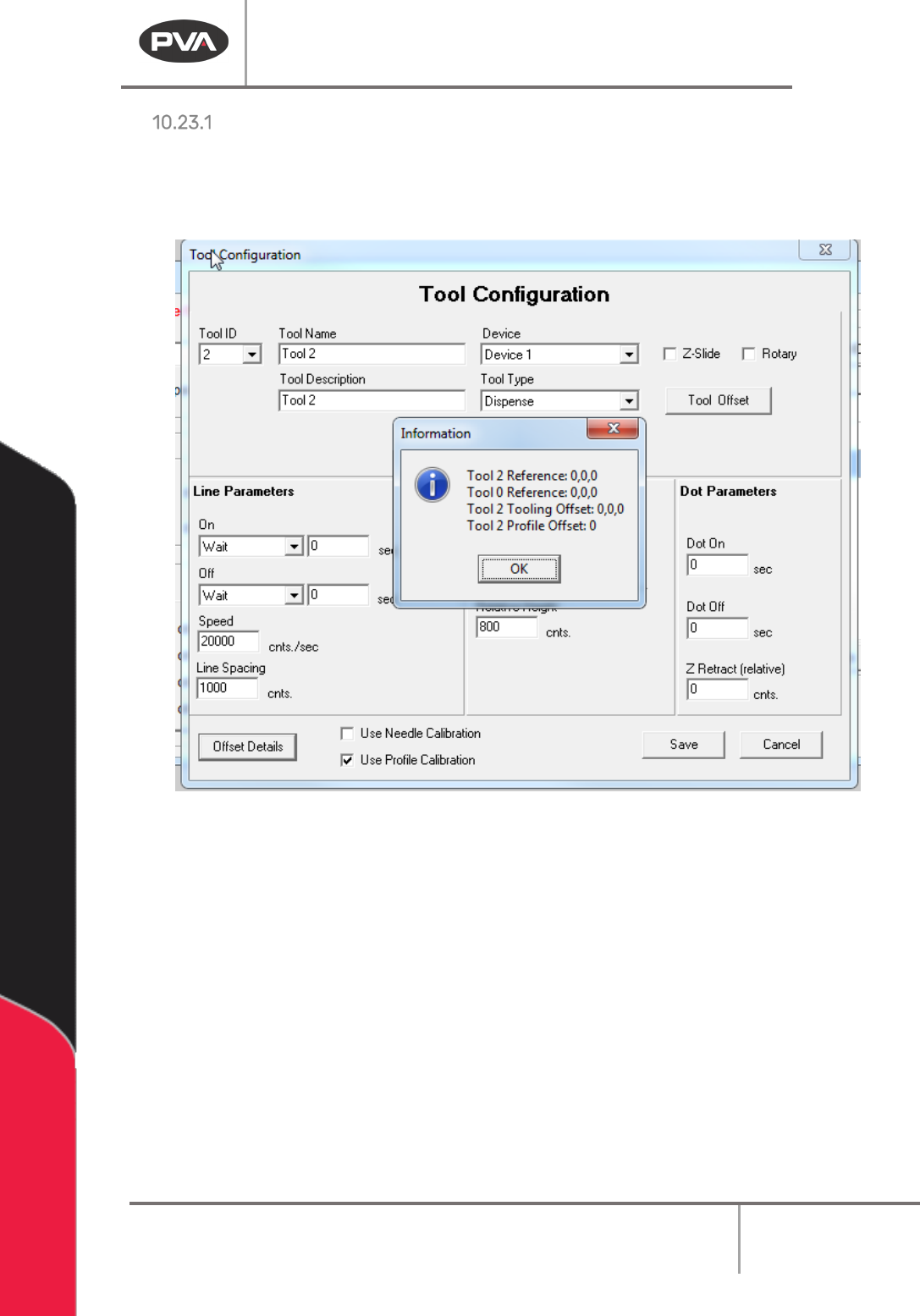
Offset Details
The offset height is shown in PathMaster’s Tool Configuration window and set in the
Camera Offset Training window. Refer to Section 6.6.5 for more information.
• Select the Offset Details button to be shown the related tool offset.
Figure 133: Example Tool Offset
Run Tool Reference – This is the absolute position where the Run Tool is positioned to
calculate the tool offset.
Teach Tool Reference – This is the absolute position where the Teach Tool is positioned to
calculate the Tool Offset.
Run Tooling Offsets – This is the difference in position between the Teach Tool and the Run
Tool (Tool Offset).
Tool Profile Offset – This is the difference between the Profile Z Common reference and
the tip of the Run Tool (Profile Offset).
Machine Operation Manual
Revision L /
February 2020
Page 112 of 200
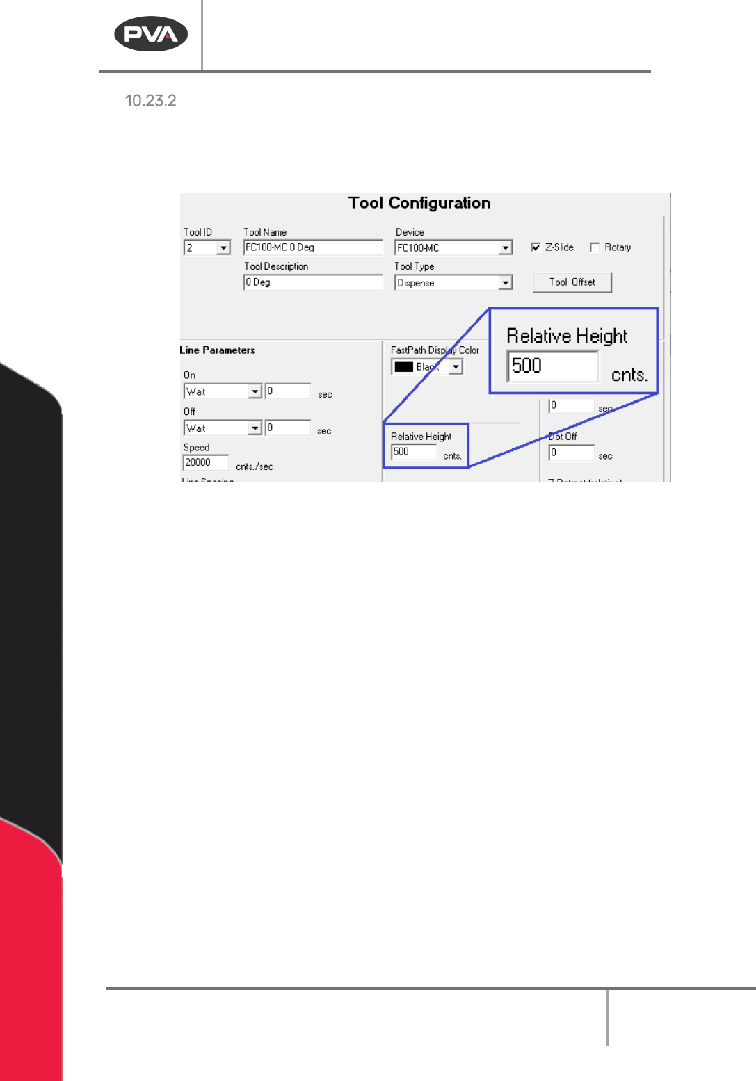
Relative Height
The Relative Height is shown in PathMaster’s Tool Configuration window (Figure 134). This
value must be correctly set or the workpiece or workcell could be damaged. This value can
be found in
Setup -> Machine Parameters -> Tool Parameters
for each tool.
Figure 134: Relative Height Input Box