PathMaster-REV-L-4.5-1.pdf - 第192页
Machine Operati on Manual Revision L / February 2020 Page 192 of 200 Figure 215 : Center of Rot ation This will up date the Gal il resou rce associ ated wi th the cente r of rotatio n for the W - axis relative to the cam…
Machine Operation Manual
Revision L /
February 2020
Page 191 of 200
13. After the position is taught a confirmation screen will be shown for the X and Y
positions Select “
Next”. Another screen will confirm the Z-position.
Figure 213: Remove Threaded Spike
14. Turn the door bypass “Off” and open the door.
15. Turn the threaded spike counterclockwise to remove it.
16. Close the door.
17. Select “Next”.
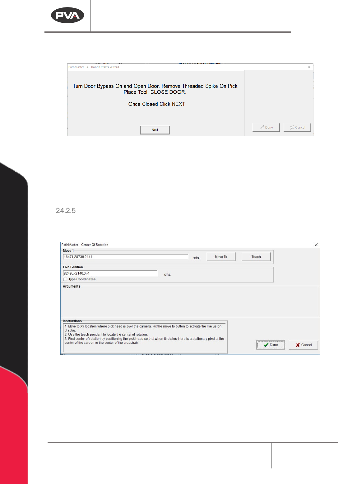
Center of Rotation
1. When you hit the “Move to” button the camera goes live and feed is displayed in the
vision tab.
Figure 214: "Move To" Button
2. To teach the center of rotation, use the teach pendant to move the X,Y location so
that when you move the W-axis the exact center of the image is stationary and
everything is rotating around it (center of rotation).
3. When this location correct push the “Teach” button on the teach pendant.
Machine Operation Manual
Revision L /
February 2020
Page 192 of 200
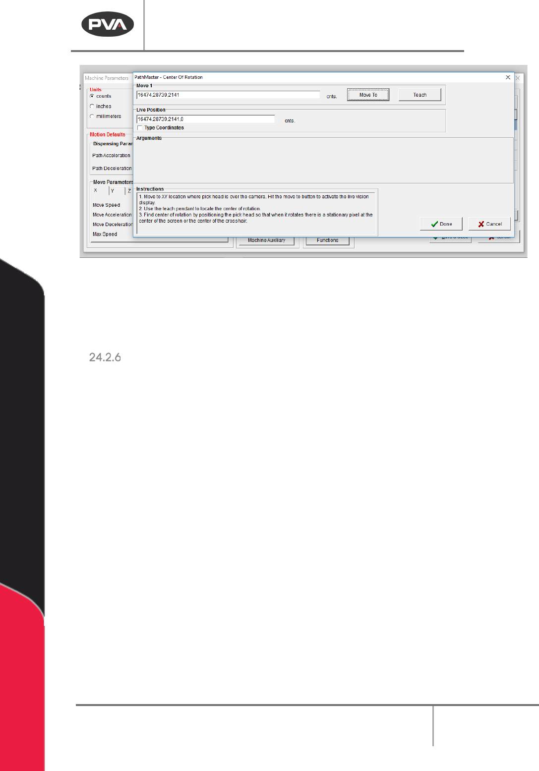
Figure 215: Center of Rotation
This will update the Galil resource associated with the center of rotation for the W-axis
relative to the camera.
4. Select the done button. The camera and light will turn off.
Part Thickness
Use the Part Measurement plugin to set the part thickness. You must do this for both the
substrate and the component.
1. In PathMaster, select
Plugins->Part Measurement
from the main menu.
2. When the Part Measurement window opens, select the “Perform Check” box.
3. Select Substrate or Component from the Operation drop down menu.
4. Highlight the section of path that has the Part Measurement plugin and run it in
manual mode.
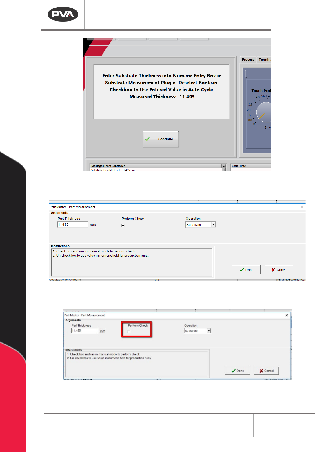
After the check is done, the Part Thickness value will be shown on the Portal screen.
Machine Operation Manual
Revision L /
February 2020
Page 193 of 200
Figure 216: Measured Thickness
5. Enter the value in the Part Thickness box.
Figure 217: Part Thickness in mm
6. Deselect the “Perform Check” box.
Figure 218: Perform Check Box