PathMaster-REV-L-4.5-1.pdf - 第89页
Machine Operati on Manual Revision L / February 2020 Page 89 of 2 00 Figure 99 : Teach a Point As each segme nt is cre ated, i t is added to the comman d list on the l eft of the P olyline program table. The polyline is …
Machine Operation Manual
Revision L /
February 2020
Page 88 of 200
PolyLine (Legacy and DMC2000)
A PolyLine is a path made of 2 dimensional lines, arcs, and circles. PolyLines are used when
it is necessary to change direction quickly at high speeds during a dispense. Paths with
lines, arcs, and circles will have smoother movement and more uniform corners and circles
if created as a polyline.
There are two ways to make a polyline. Individual path segments can be made and then
changed to a polyline, or via the Polyline tool.
New PolyLine
When teaching a segment in a polyline, the last point of the previous segment will be used
as the first point of the new segment. For example, only two points of a polyline arc need to
be taught (if it is not the first segment of the polyline) because the first point will be the
last point of the previous segment.
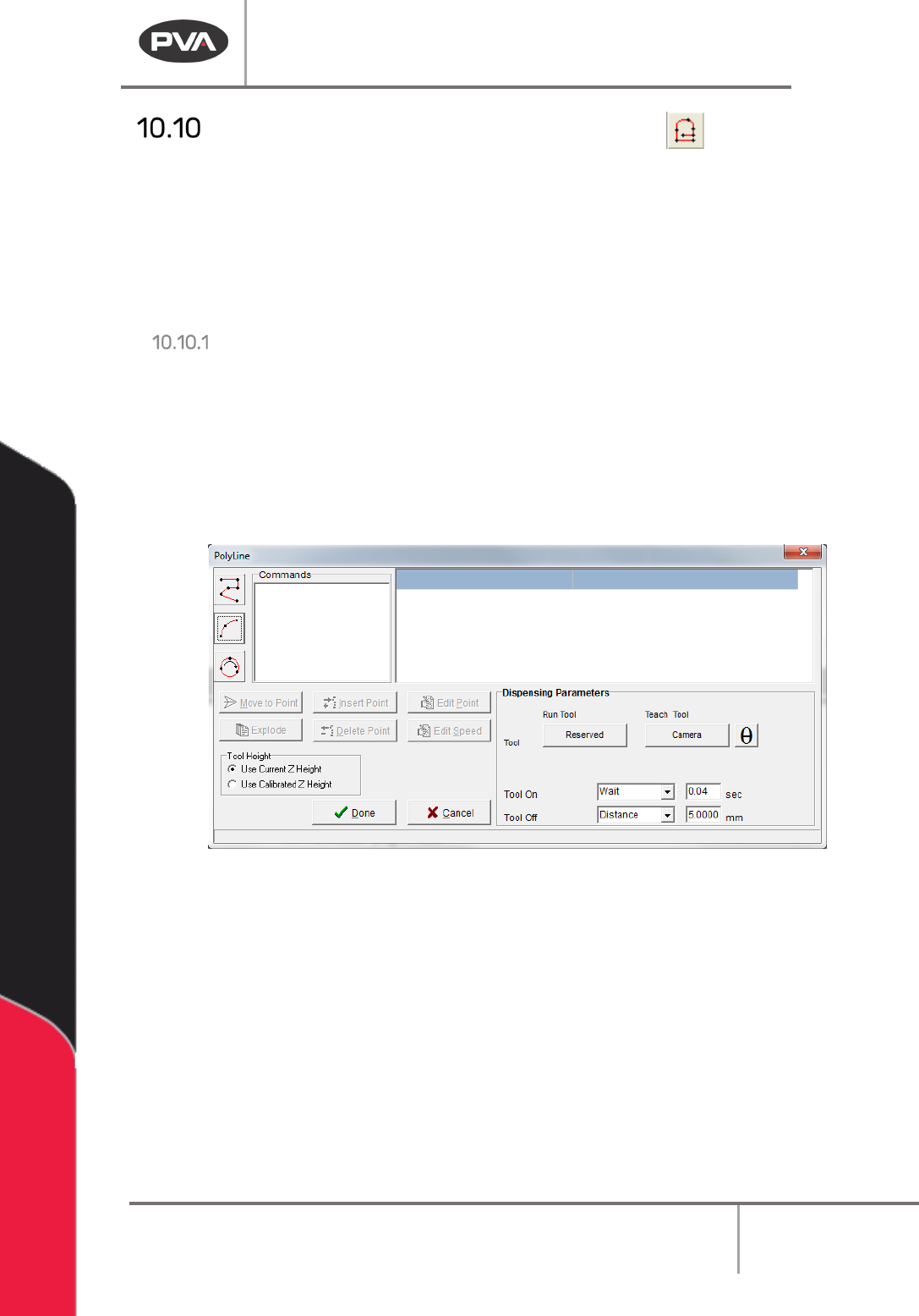
4. Open the Polyline function from the top menu
Teach > PolyLine.
5. Select a programming tool from the toolbar on the left.
Figure 98: PolyLine Window
6. Teach the points required for the tool selected.
7. Set the Path Speed.
Machine Operation Manual
Revision L /
February 2020
Page 89 of 200
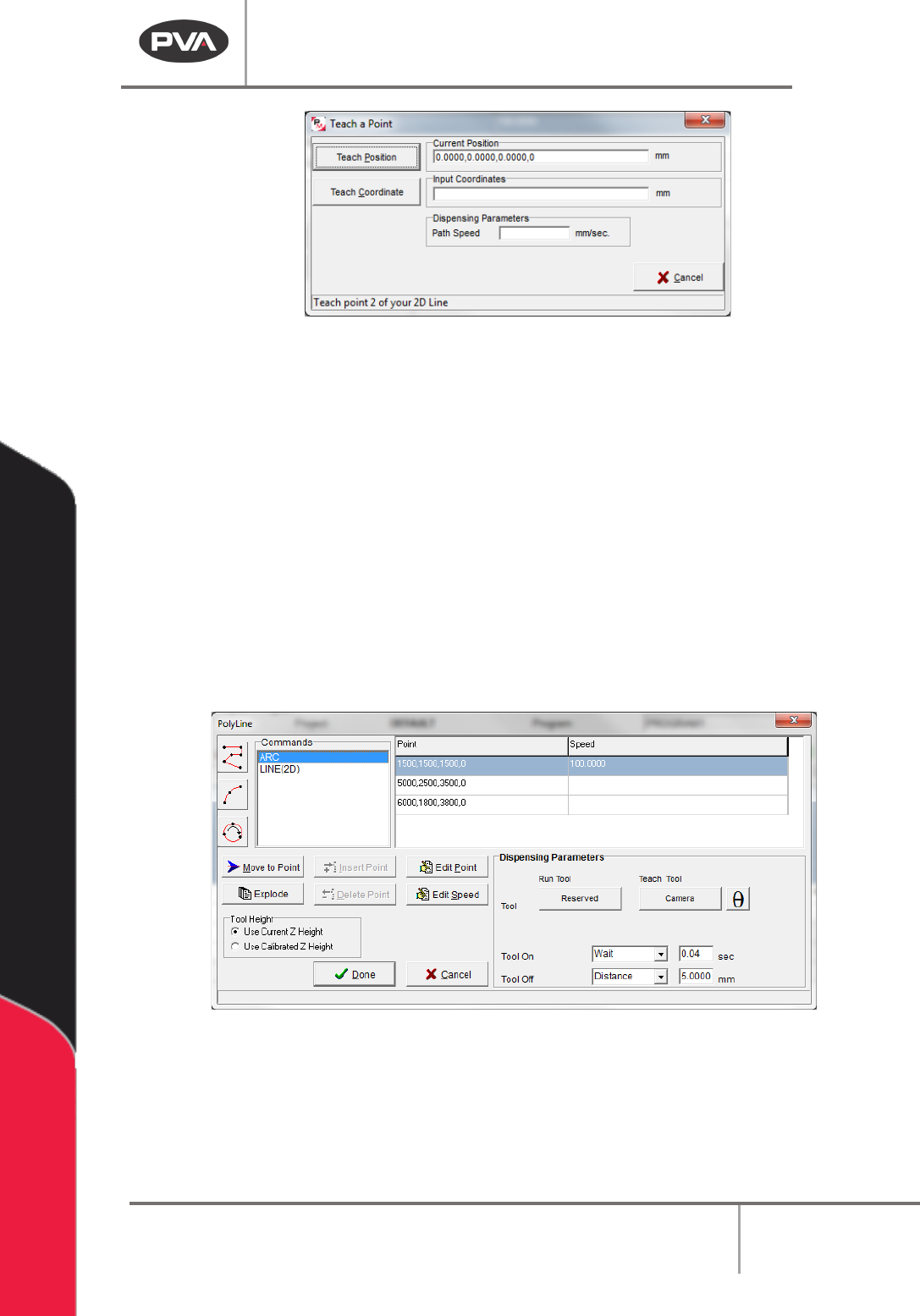
Figure 99: Teach a Point
As each segment is created, it is added to the command list on the left of the Polyline
program table. The polyline is limited to 2047 points for all segments.
8. Select a command from the list of commands.
9. Set the Dispensing Parameters.
10. Select “θ” to move the selected tool to the calibrated W-axis position (theta).
NOTE: The “θ” button will only be available on 4-axis machines. When using the “Teach
Tool” (virtual tool 0), it is not necessary to select this button.
11. Select a segment in the command list and select the “Edit Point” button or the “Edit
Speed” button to edit the points and speed for each segment.
12. The Polyline can also be exploded into individual path segments and modified on the
main PathMaster® program table.
Figure 100: PolyLine
13. Select “Done” to save the completed polyline or select “Cancel” to exit and not save
changes.
14. To edit, double click on the path segment and change the command in the edit
window. Refer to Section 7.5.
Machine Operation Manual
Revision L /
February 2020
Page 90 of 200
From Selected Line
15. To create a polyline from individual path segments, select the path segments to
include in the Polyline.
16. Select the Teach menu.
17. Select
Polyline -> From Selected Lines
.
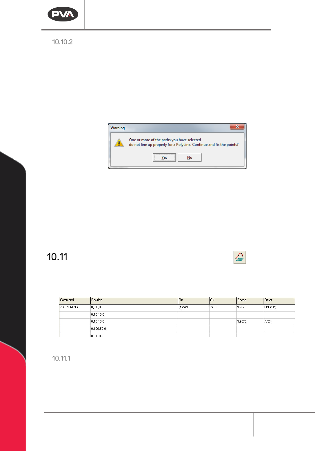
If the endpoints of the path segments do not match up, PathMaster® will ask to match up
the endpoints. If you do not to match up the endpoints the polyline will not be made. If you
select match up the endpoints, the polyline will use the best fit.
Figure 101: PolyLine Point Match Up
When a polyline is made from individual path segments, the tool parameters will be from
the first path segment in the series. The speeds for each path segment will be kept.
WARNING! PathMaster® will use the tool used in the first segment for all the segments.
Make sure all individual paths segments in a polyline use the same tool.
18. To edit a polyline, double click on the path and change the command in the edit
window. Refer to Section 7.5.
Polyline3D (Legacy and DMC2000)
A Polyline3D is a single continuous dispensing path that allows motion in the X, Y, and Z
Axes. There are two ways to make a polyline. Individual path segments (2D/3D lines or
Arcs) can be made and then changed to a polyline, or you can use the Polyline tool.
Figure 102: Programmed 3D Polyline Command
New Polyline3D
When you teach a segment in a polyline, the last point of the previous segment is used as
the first point of the new segment. For example, it is only necessary to teach two points of
a polyline arc (that is not the first segment of the polyline) because the first point will be
the last point of the previous segment.