PathMaster-REV-L-4.5-1.pdf - 第47页
Machine Operati on Manual Revision L / February 2020 Page 47 of 200 Figure 40 : Profile Ca libration Setup 3. Next, ru n the Profil e Plung er Locate Se quence by pressi ng CTRL + S o n the keyboard . It is not nece ssar…
Machine Operation Manual
Revision L /
February 2020
Page 46 of 200
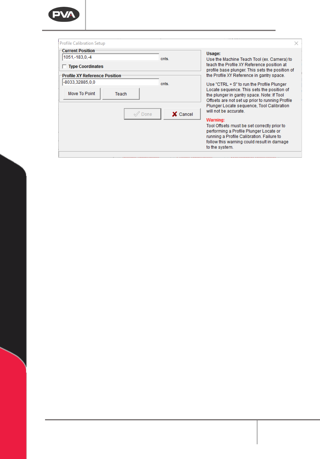
WARNING: The tool offsets must be configured before Profile Calibration is set up. If Tool
Offsets are not configured correctly, the system could be damaged when the Profile
Plunger Locate Sequence is run.
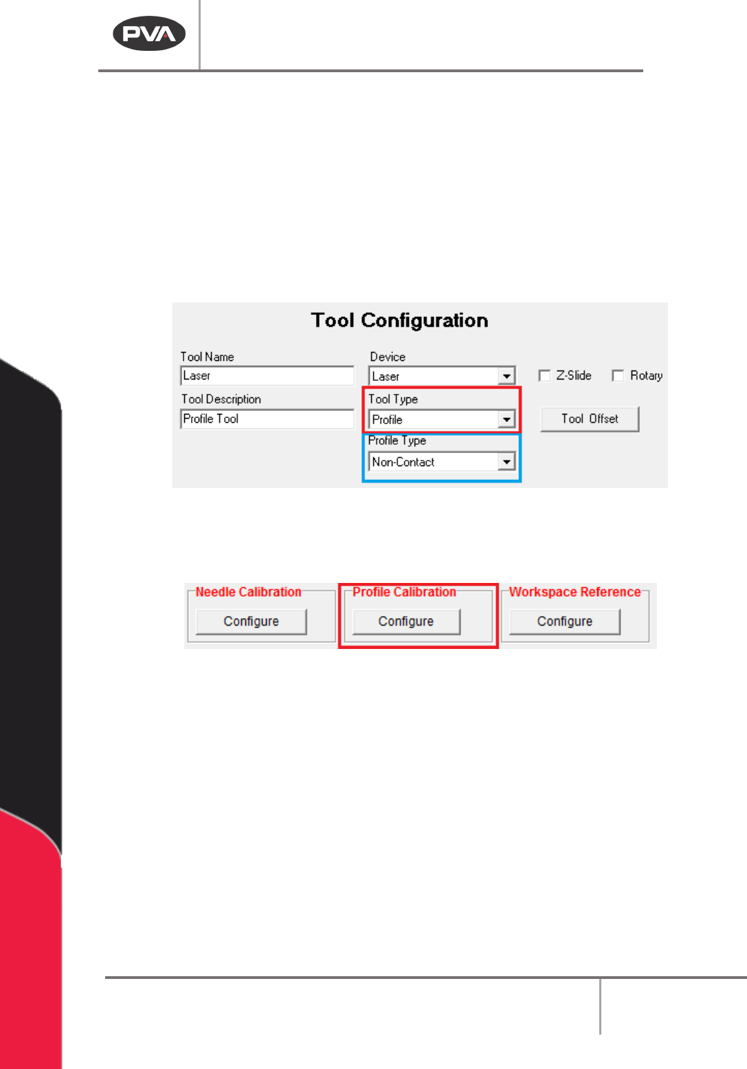
• To setup height profiling, it is necessary that all tool offsets are correctly set up,
that Needle Calibration Setup is complete (if applicable), and that a tool is set up
with the tool type of “Profile Tool” in Machine Parameters.
• When Setting up a Profile Tool Type, a second selection box is shown for the Profile
Type: Non-Contact or Contact. A selection must be made for correct operation of
the Profile Tool.
Figure 38: Profile Tool Type and Profile Type Selection
1. After the setup is complete, click “Configure” underneath Height Profiling in the
Machine Parameters window to open Profile Calibration Setup.
Figure 39: Height Profiling
2. To set the Profile XY Reference Position, line the teach tool up with a point on the
Profile Base and select the “Teach” button. Click the “Move To Point” button to
move to the last programmed Profile XY Reference position.
Machine Operation Manual
Revision L /
February 2020
Page 47 of 200
Figure 40: Profile Calibration Setup
3. Next, run the Profile Plunger Locate Sequence by pressing CTRL + S on the
keyboard. It is not necessary to run this every time a Profile XY Reference position is
set, but it must be done during initial setup, if the Profile Base is damaged or
replaced, or if the Profile Tool is damaged or replaced. The Profile Plunger Locate
sequence uses the Tooling Offset between the Teach and Profile Tools to read the
Profile Base Plunger to determine a common profile surface for all tools, called the
Profile Z Reference.
4. When the Profile XY reference position has been taught, and the Profile Z Reference
is established, select the “
Done” button, or select “Cancel” to exit and not save
changes.
Machine Operation Manual
Revision L /
February 2020
Page 48 of 200
Workspace Reference
Workspace reference is a global reference position used to help make a machine program
transport or a global offset to the local system.
To teach a workspace reference point, on a typical system, put the machine calibration
plate against the board stops and put the teach tool at the cross hair on the machine
calibration plate. The workspace reference point must reference the part workspace so
that if the part fixture changes, due to board stop location, etc., the workspace reference
point moves with it.
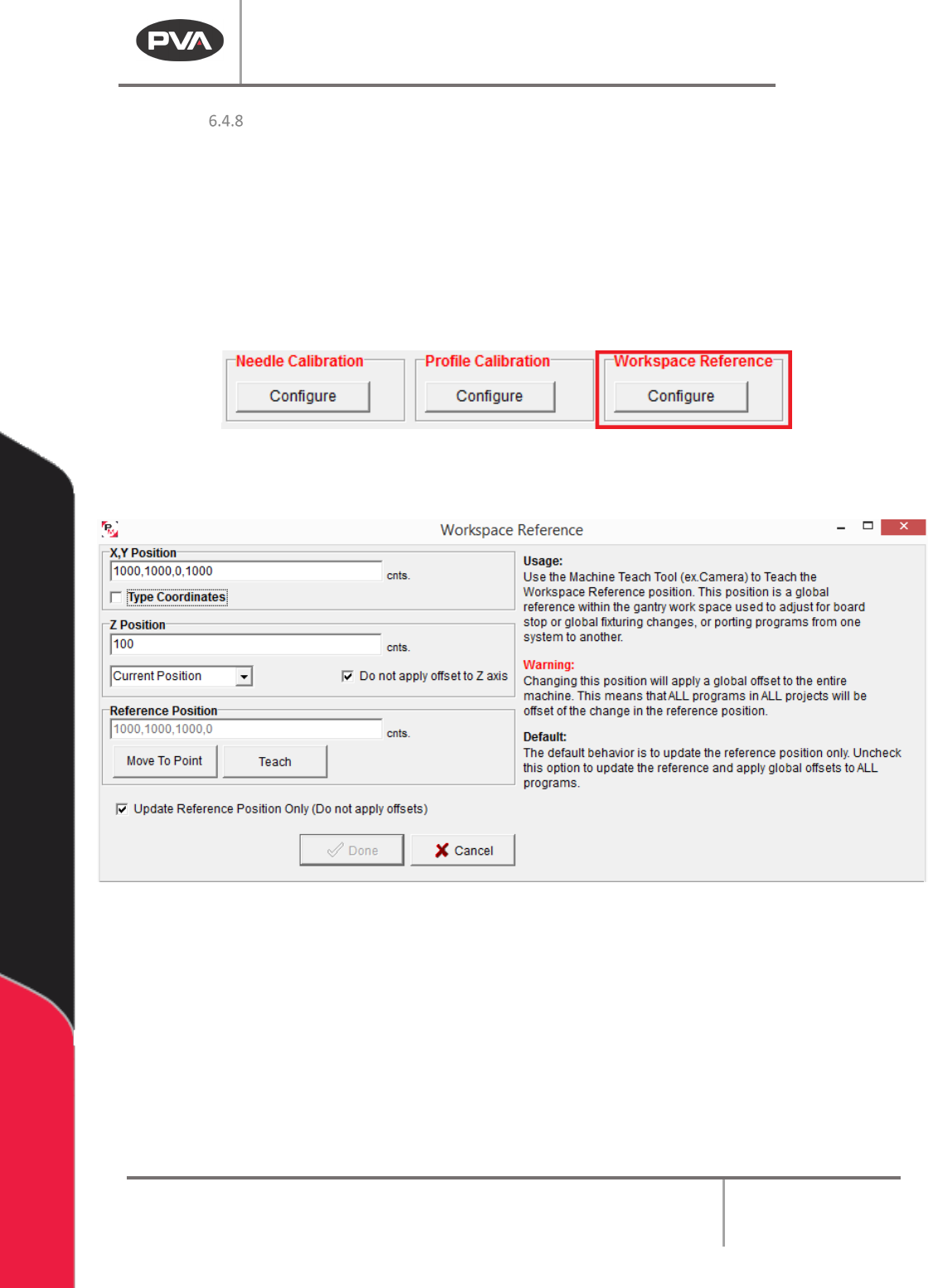
Figure 41: Workspace Reference
1. Select the Workspace Reference “Configure” button.
Figure 42: Workspace Reference Window
2. Click the “Move To Point” button to move to the workspace reference position.
3. If the Move to Point button is not in the correct location, use the teach tool to move
to the necessary workspace reference position. Click the
“Teach” button to teach
the workspace reference position.
4. The Update Reference Position Only checkbox is checked by default. This will
update the workspace reference position but not apply program offsets (The
difference between the original workspace reference and the new workspace
reference). Uncheck this box to apply global offsets to all programs.