PathMaster-REV-L-4.5-1.pdf - 第105页
Machine Operati on Manual Revision L / February 2020 Page 105 of 200 Recta ng ular Spira l This create s a square s piral pa ttern with a n area defined by t he user. This is one c ontinuo us dispense and is used when a …
Machine Operation Manual
Revision L /
February 2020
Page 104 of 200
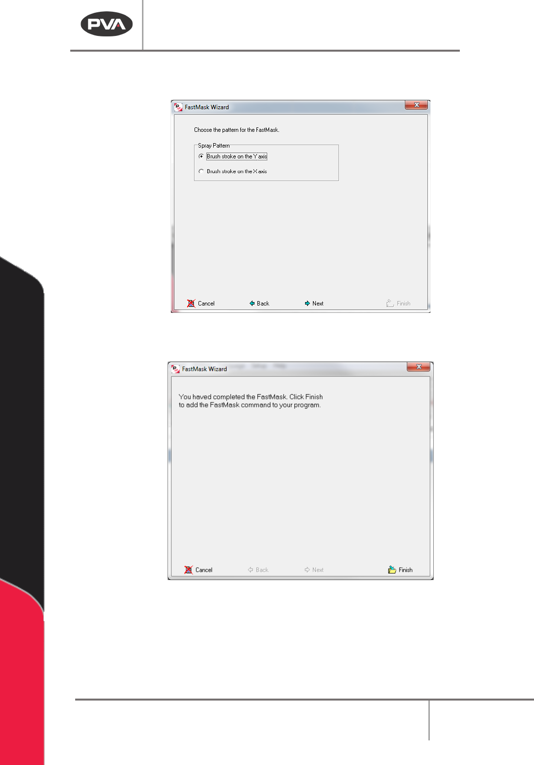
17. Select the Spray Pattern. This is the direction the tool will go when this FastMask™
pattern is used.
Figure 124: FastMask Brush Stroke Pattern
18. Select the “Next” button.
Figure 125: FastMask Complete
19. Select the “Finish” button.
The FastMask™ pattern will always start at the point taught closest to the origin of the
gantry (the smallest coordinate in the pattern).
20. To edit a FastMask, double click on the path and change the command in the edit
window. Refer to Section 7.5.

Machine Operation Manual
Revision L /
February 2020
Page 105 of 200
Rectangular Spiral
This creates a square spiral pattern with an area defined by the user. This is one continuous
dispense and is used when a material is unable to be equally spaced with the area
command. There are 3 points, the 1st point is the start, the 2nd point is direction, and the
3rd point gives the size. The Z-axis does not change position in this path.
Figure 126: Rectangular Spiral Programmed
1. Open the Rectangular Spiral function.
Figure 127: Teach Rectangular Spiral
2. Select the Run Tool. Select (double click) the necessary tool from the Tool Selection
window. Refer to
Figure 68.
3. Select the Teach Tool if necessary. Select (double click) the necessary tool from the
Tool Selection window. Refer to
Figure 68.
4. Select “θ” to move the selected tool to the calibrated W-axis position (theta).
NOTE: The “θ” button will only be available on 4-axis machines. When you use the “Teach
Tool” (virtual tool 0) it is not necessary to select this button.
5. Select the Surface from the drop-down menu. In some units, you can set the
Relative Height.
6. Put the necessary value in the Path Speed box.
7. Teach the points. Point 1 is where the path starts. Point 2 is the direction of the
path. Point 3 uses the diagonal distance between 1 and 3 to find the size.
8. Set the Tool On and Tool Off to “Wait” or “Distance” and set the time or distance in
the box.
9. Set the Line Spacing.
10. Select “Done” to save the changes or “Cancel” to exit and not save changes.
11. To edit, double click on the path and use the edit window. Refer to Section 7.5.
Machine Operation Manual
Revision L /
February 2020
Page 106 of 200
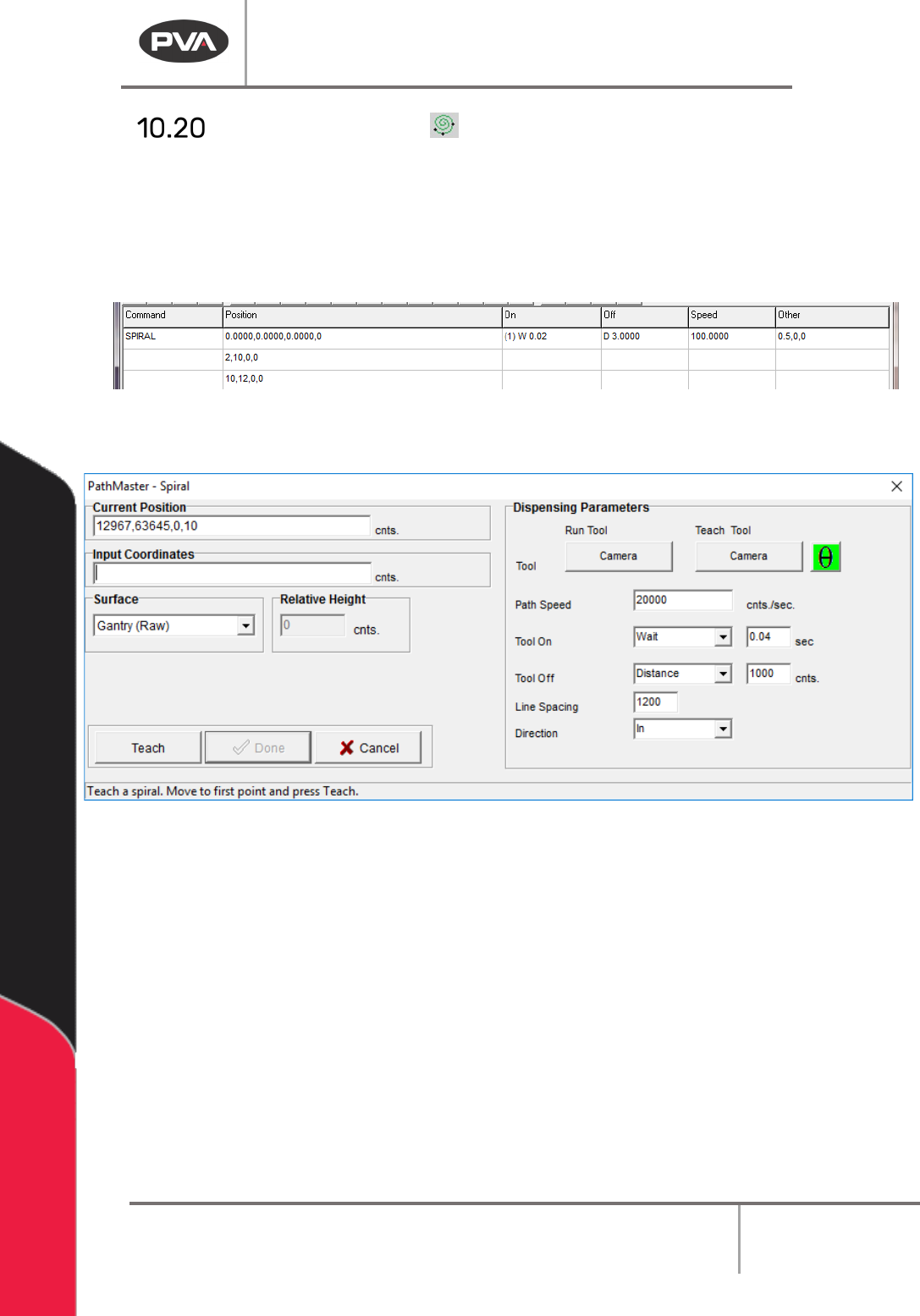
Circular Spiral
This creates a spiral pattern with an area defined by the user. The command is taught like
an arc command. It uses 3 points where the 1st point is the start, the 2nd point is direction,
and the 3rd point forms a diagonal with the 1st point to determine size. In this tool, line
spacing is the pitch or distance between arcs and direction refers to in or out direction of
the path. The Z-axis does not alter its position during the path.
Figure 128: Spiral Programmed
1. Open the Spiral function.
Figure 129: Teach Spiral
2. Select the Run Tool. Select (double click) the necessary tool from the Tool Selection
window. Refer to
Figure 68.
3. Select the Teach Tool. Select (double click) the necessary tool from the Tool
Selection window. Refer to
Figure 68.
4. Select “θ” to move the selected tool to the calibrated W-axis position (theta).
5. Select the Surface from the drop-down menu. In some units, you can set the
Relative Height.
6. Put the necessary value in the Path Speed box.
7. Set the Path Speed.
8. Teach the points required for the tool selected. Point 1 is where the path will start.
Point 2 is the direction of the path. A diagonal line between point 1 and point 3 gives
the size of the rectangle.