PathMaster-REV-L-4.5-1.pdf - 第19页
Machine Operati on Manual Revision L / February 2020 Page 19 of 2 00 Save Sett ings and Data base F old ers Before the Program Of fsets ca n be ap plied, a b ackup of the ma chine d atabase is cre ated. The backup file w…

Machine Operation Manual
Revision L /
February 2020
Page 18 of 200
Computer and Workcell Communication
The workcell communicates with the PC through RS-232 or Ethernet. All PVA Portal
systems communicate through Ethernet. Standalone systems communicate through RS-
232 but Ethernet can be used if the workcell has a Galil DMC2200, DMC4000, or DMC4200
series motion controller.
WARNING! The computer must be at the same ground potential as the workcell.
Ethernet Communication
The PC can communicate with the workcell over Ethernet directly, with an Ethernet cross-
over cable, or through a switch (Galil Series DMC2000, DMC4000, DMC4200 required.) The
Galil controller must remain on a localized subnet that does not see traffic from external
networks or devices. The only devices that can be on the Galil subnet are the PC and
remote I/O controllers. Connect all other devices through a separate NIC on the PC.
Switch
Position
Description
MRST OFF Master Reset Switch
10B OFF Ethernet Connection Speed
Ethernet OFF Unsolicited MG’s (Default)
Table 1: DMC-2200 Dip Switch Settings for Ethernet
Device
Address
Subnet Mask
Computer
100.100.100.100
255.255.255.0
Galil
Controller
100.100.100.101
Default
Remote I/O
100.100.100.102
Default
Table 2: Typical Ethernet Addressing

Machine Operation Manual
Revision L /
February 2020
Page 19 of 200
Save Settings and Database Folders
Before the Program Offsets can be applied, a backup of the machine database is created.
The backup file will save with the date and time. Where the file is saved depends on the
operation. Refer to the Database Folders chart below for details. When the offsets are
applied, the database is saved and programs are exported to a DMC format for use with
PartManager (this is the equivalent of
Save For Part Manager
option in PathMaster®,
version 4.1).
NOTE: Some auto backup and save features can be changed in the PathMaster.ini. Contact
PVA for details.
Table 3: Database Folders
Folder
Description
\PathMaster\DB Active System Database
\PathMaster\DB\Daily Daily Auto Backups
• Created once per day on program launch
• File name AB_<Date>_<Time>.bck
\PathMaster\DB\Machines
Machine Backups
• Created on import of machine database
• File name <Machine name>.bck
• Multiple Backups are created if Multi Machine
database is imported
\PathMaster\DB\NeedleCalibration Needle Calibration Backups
• Created prior to running needle calibration
• File Name <Date>_<Time>_TOOL_<TL_ID>.bck
• If multiple tools, file name will contain multiple
Tool IDs.
\PathMaster\DB\ToolOffset Tool Offset Backup
• Created prior to Tool Offset Setup or Tool
Change function
• File Name <Date>_<Time>_TOOL_<TL_ID>.bck
\PathMaster\DB\WorkspaceReference
WorkSpace Reference Backup
• Created prior to Teaching a Workspace
Reference
• File Name <Date>_<Time>.bck
\PathMaster\DB\Transfer
Machine Transfer Backup
• Created prior to Export -> Machine -> Transfers
• Filename <Date>_<Time>.tfr
Machine Operation Manual
Revision L /
February 2020
Page 20 of 200
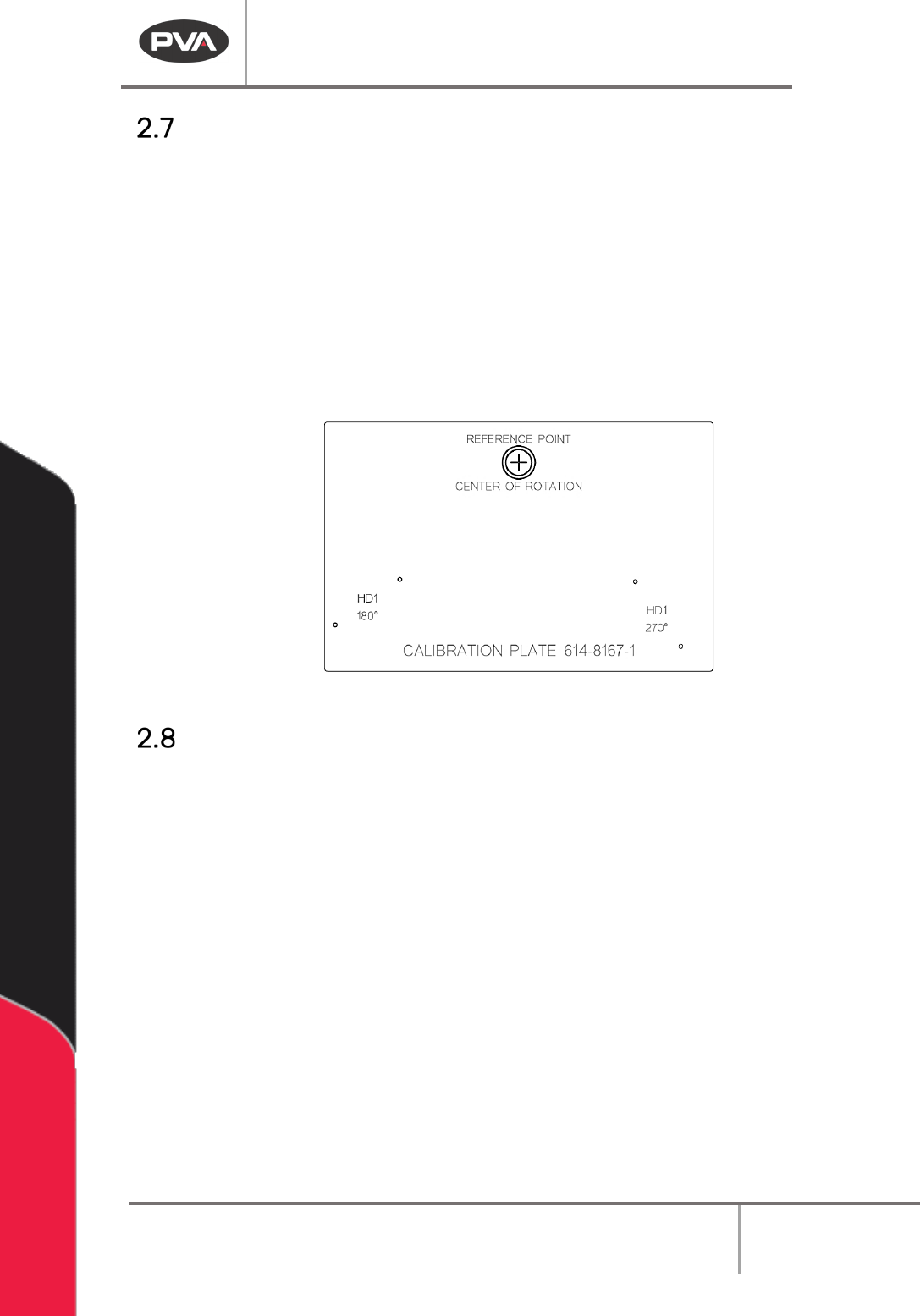
Calibration Plate
Every system should have a recognizable workspace reference position. Standard systems,
with conveyors or flex fixtures, use a calibration plate (see below). Custom systems and
systems with non-standard part fixtures will have a defined workspace reference position,
but may or may not use the standard calibration plate.
• To use the standard calibration plate, put the plate on the conveyor or flex fixture so
it is against the fixed rail and the hard stop or board stop.
• The purpose of the calibration plate, as it relates to PathMaster® 4.2 and 4.3, is to
define a consistent workspace reference position. This is very important to the
efficacy of machine transportability.
Figure 4: Calibration Plate
Path Program Planning Tips
• Look at the workpiece to be programmed and find a place to start the path.
• Plan the path program on paper with a diagram or plotted points.
• Select the tool (dispense valve, spray valve, jet) for each path.
NOTE: The first point and direction may not be best and it may be necessary to program
the path again.
• Include the active tool operations for each path, ex: Rotate A/B, Tool Up/Down.
• Put the workpiece in the workcell in a repeatable location and make sure it is parallel
with the gantry.
• Insert comments into the program for future editing or other users. Comments are
shown in red text.
NOTE: If a stop or dwell must be added at one of the points after a path is completed, the
path must be broken into two paths or be programmed again.