PathMaster-REV-L-4.5-1.pdf - 第52页
Machine Operati on Manual Revision L / February 2020 Page 52 of 2 00 Add a Tool 1. Select Setup - >Ma chine P aramete rs from the Main me nu to open the M achine Parameters window. 2. To add a new virt ual tool, click…
Machine Operation Manual
Revision L /
February 2020
Page 51 of 200
Virtual Tools
PathMaster® can have an unlimited number of virtual tools configured. All virtual tools are
related to a physical device in the system. A device can be saved with specific settings as
several different virtual tools.
For example, in a 4-axis system, Tool 1 can be device A with a theta rotation of 0°. Tool 2
can be device A with a theta rotation of 90°. The same device is used for Tool 1 and 2 but
the valve settings are different.
The different theta positions of the virtual tools changes how the physical device relates to
the teach tool. The difference in position relationship is called the tool offset. Refer to
Section 6.6.5 for more information.
If the teach tool is enabled, you must create Virtual Tool 0 first for Device 0 before you can
create additional virtual tools.
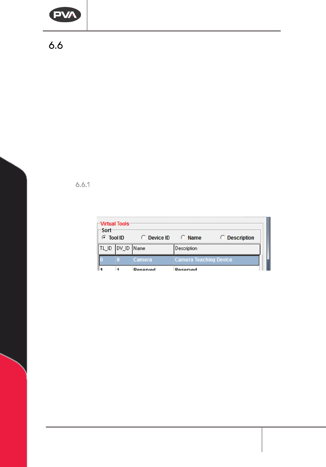
Sort
With the Sort radio buttons, you can arrange how you view the Virtual Tools in the system.
You can sort the virtual tools by
Tool ID, Device ID, Name, or Description.
Figure 45: Sort Options
• Select the necessary label to sort the virtual tools.
Machine Operation Manual
Revision L /
February 2020
Page 52 of 200
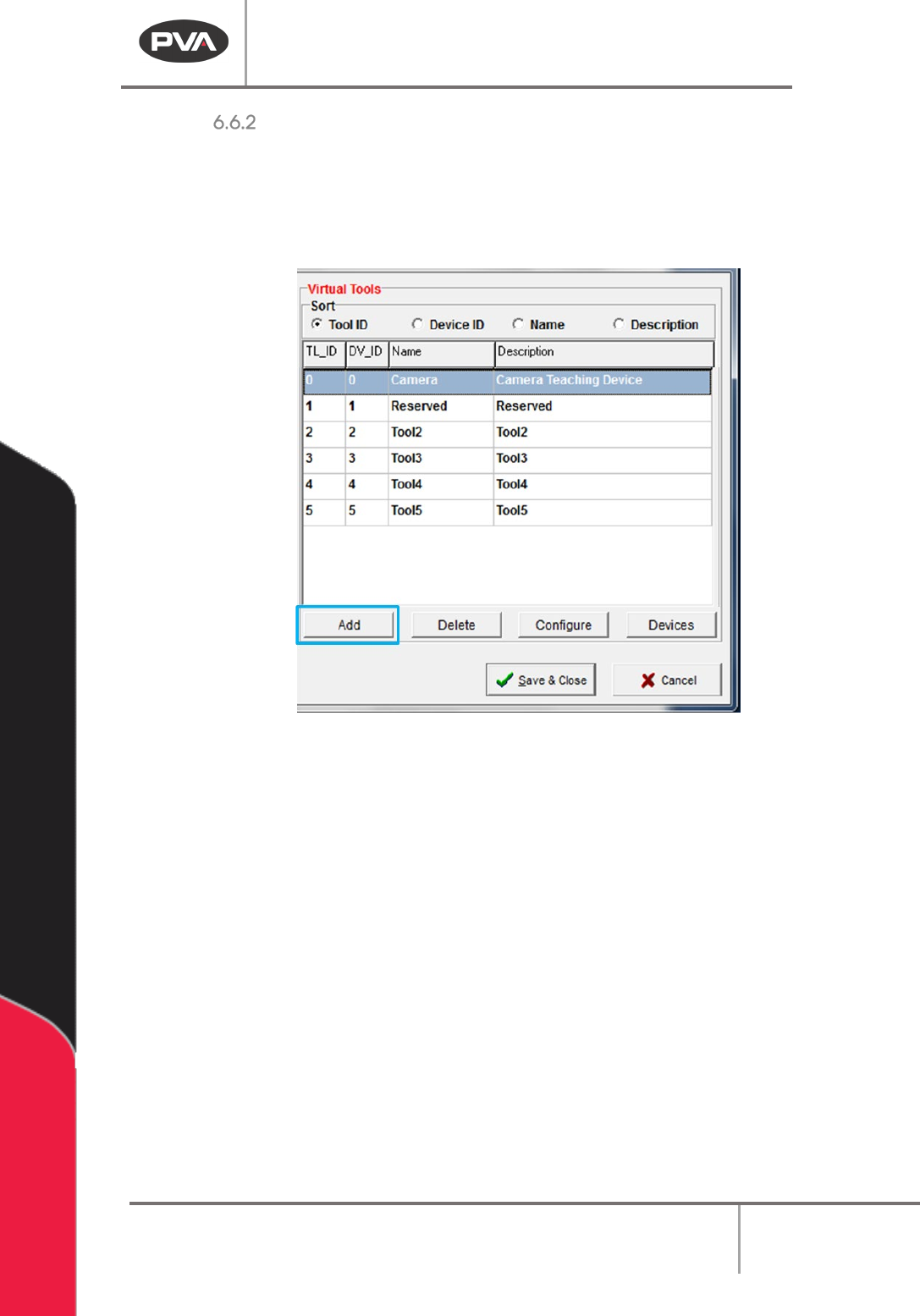
Add a Tool
1. Select
Setup->Machine Parameters
from the Main menu to open the Machine
Parameters window.
2. To add a new virtual tool, click the “Add” button in the Virtual Tools section of
Machine Parameters.
Figure 46: Add a Virtual Tool
3. The Tool Configuration menu will open; refer to Section 6.6.4 for more information
about how to correctly configure a virtual tool.
Machine Operation Manual
Revision L /
February 2020
Page 53 of 200
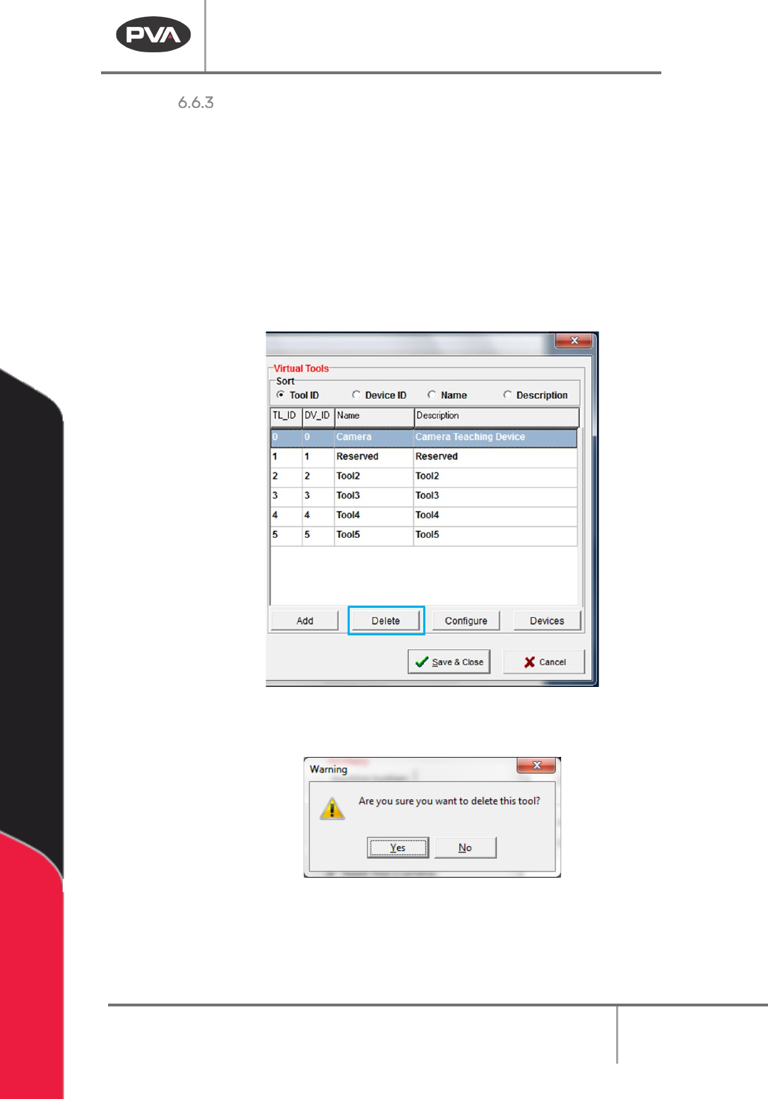
Delete a Tool
Select
Setup->Machine Parameters
from the Main menu to open the Machine Parameters
window.
WARNING: If a Virtual Tool was used in a path before it is deleted you will have to update
that path with a different virtual tool. If you play a path that uses a deleted virtual tool
there may be unintended consequences.
1. To delete a virtual tool, select the tool in the Virtual Tools section of Machine
Parameters window.
2. Click the “Delete” button.
Figure 47: Select Virtual Tool and Delete
3. A warning window will be shown, click “Yes”.
Figure 48: Delete Tool Window
A deleted tool ID will go to a reserved state. You will have the option to use the deleted tool
ID when you create a new virtual tool.