PathMaster-REV-L-4.5-1.pdf - 第85页
Machine Operati on Manual Revision L / February 2020 Page 85 of 200 Figure 93 : Polyline Line S egment Tea ching 5. Use the C oordina te Selec tion radio bu ttons a nd Surface dropdo wn sel ection to Z coordinate option …
Machine Operation Manual
Revision L /
February 2020
Page 84 of 200
PolyLine (DMC 4000)
A Polyline is a path made of lines and arcs. Polylines are used when it is necessary to
change direction quickly, at high speeds, during a dispense. Polyline, in Pathmaster® 4.3,
uses surface height readings (taught before a polyline is used). Surface Height readings
and the Calibrated Z Height of a tool (Section
Error! Reference source not found.), account
for differences in individual part height and paths are adjusted to dispense correctly.
New Polyline
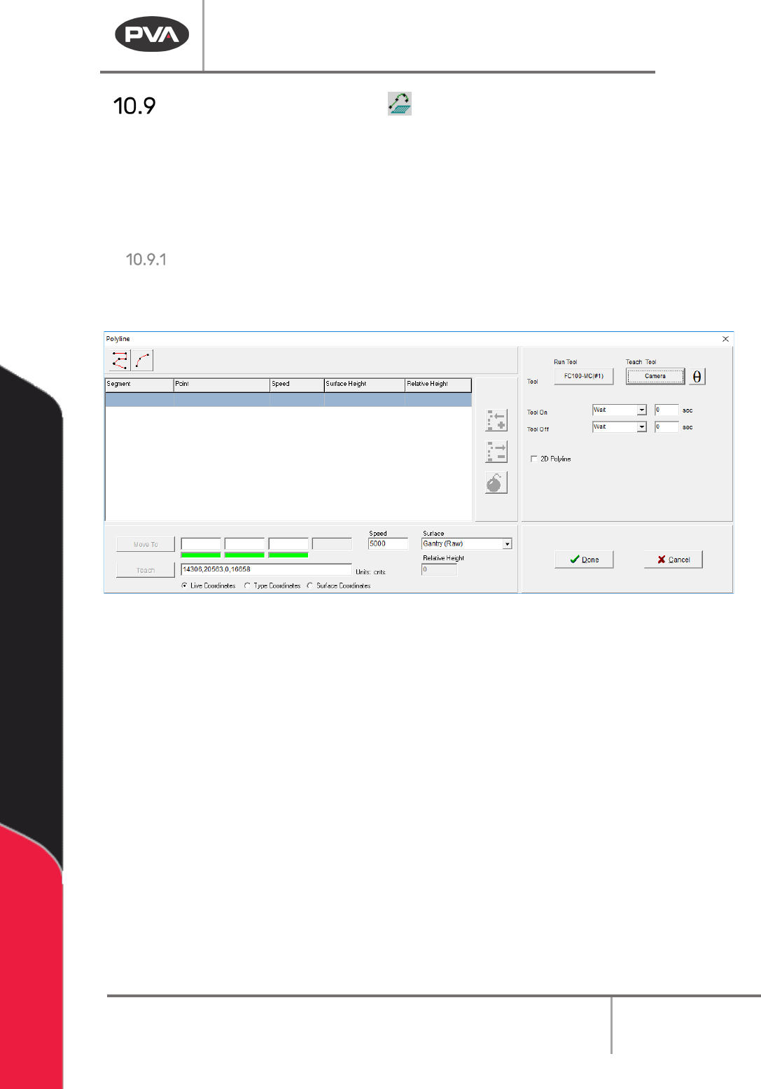
1. Click on the Polyline or select Teach > Polyline > Create New from the Main Menu to
open the Polyline Teach Interface.
Figure 92:PolyLine Teach Window
2. The Bomb button ‘explodes the polyline’. All the taught segments and arcs move
into the main path program as separate segments. When a line is exploded, the
height profiling feature cannot be used.
3. When 2D Polyline is enabled, a single Z height is taught for all the polyline segments.
Select the “
2D Polyline” checkbox to use this option.
4. Select either a Polyline or Arc from the top of the Polyline teach window. Follow the
prompts to teach the points.
Machine Operation Manual
Revision L /
February 2020
Page 85 of 200
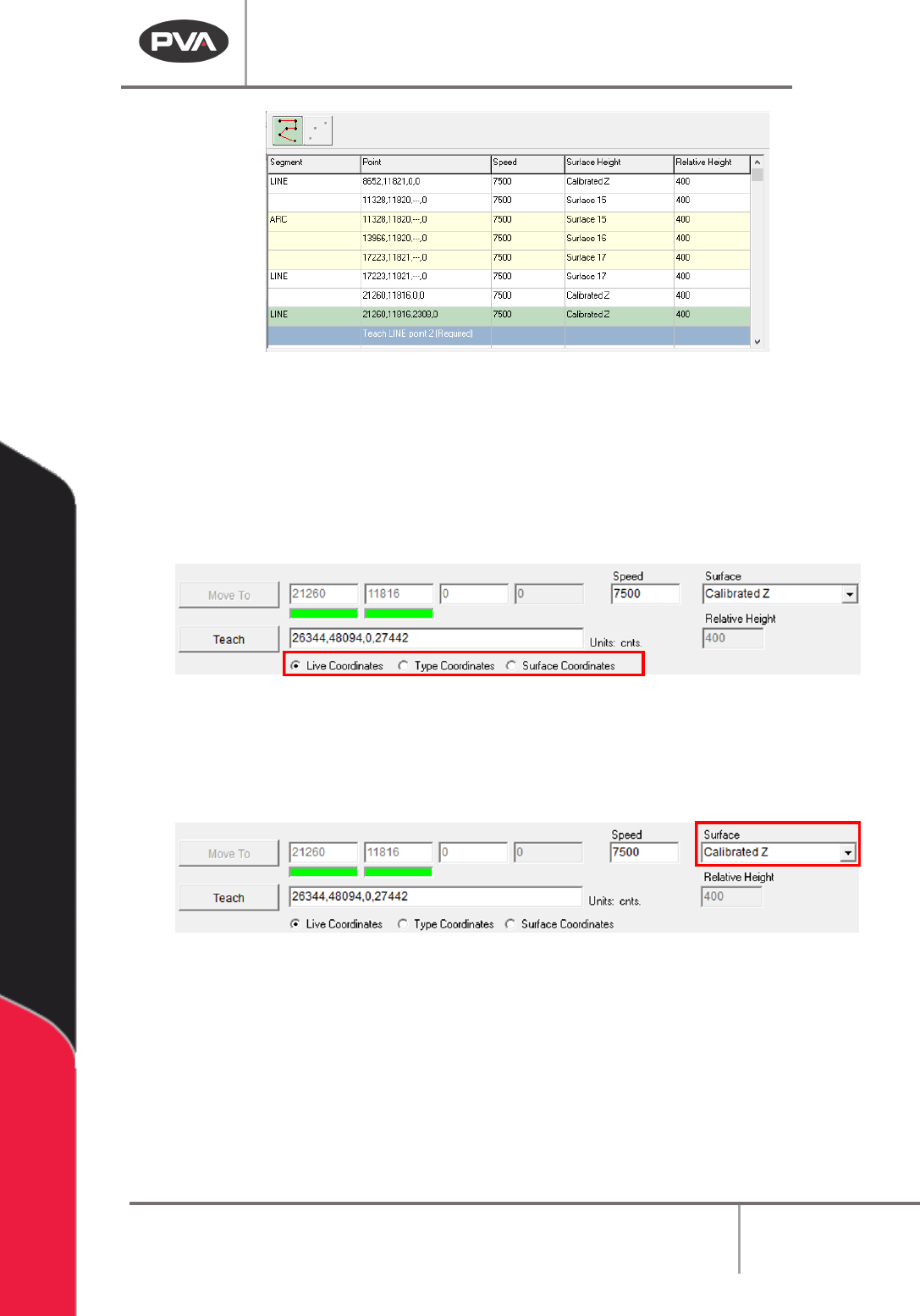
Figure 93: Polyline Line Segment Teaching
5. Use the Coordinate Selection radio buttons and Surface dropdown selection to Z
coordinate options. The radio buttons select between:
Live Coordinates: The end effector’s current gantry position.
Type Coordinates: User types in the coordinates with the keyboard.
Surface Coordinates: Where the Surface Height commands, that are valid for this
polyline, were taught.
Figure 94: Teach Radio Buttons
NOTE: Only surfaces that are in the program grid and are in the path program before the
point of insertion of the polyline will be in the dropdown.
6. Use the Surface drop-down menu to set the Z-plane for a selected Polyline point.
Figure 95: Teach Surface Dropdown
• Gantry (Raw) uses the Z coordinate exactly as it was taught.
• Gantry (Relative) uses the Z coordinate that was taught, and subtracts the “Relative
Height” numeric field’s current value.
• Calibrated Z uses the Run Tool Reference Z for the current run tool, and subtracts
the global “
Relative Height” set for that tool in Tool Configuration.
Machine Operation Manual
Revision L /
February 2020
Page 86 of 200
• Use Last uses the Z height of the previous Surface used in the Polyline. The first
point of a new Polyline cannot use this selection.
• Custom Surface uses the XY coordinates of the Surface command that shares the
same name and uses the Z height and the current run tool’s “
Calibrated Z” to set the
dispense Z height.
NOTE: Surfaces are named in the Path Segment before the Polyline being taught.
7. Click the green highlighted button above the Polyline Segment table to end the line.
8. Select the “Speed” column for an individual segment and type the value to change
it. Highlight multiple segments to change multiple values.
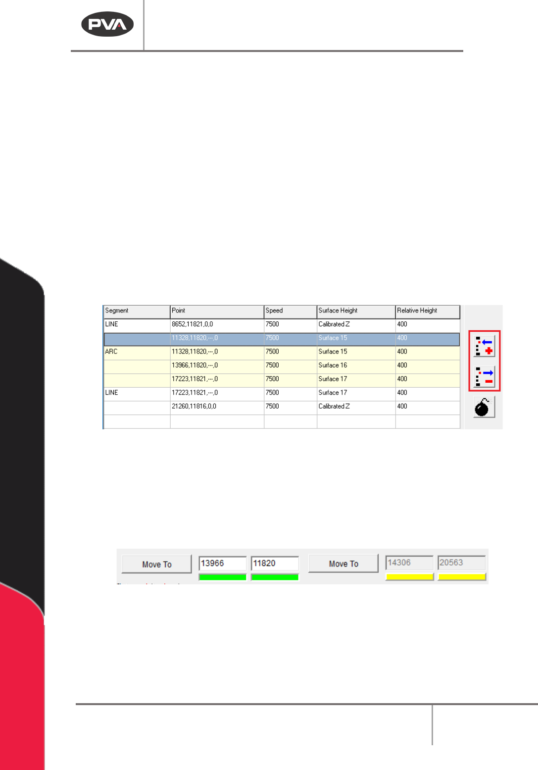
9. To edited line segments, use the buttons to the right of the Polyline Segment table.
The top button is used to add a new point into a line, and the bottom button to
remove a single point from a line, or remove an entire arc.
NOTE: After a new point is taught to a line, the segment is de-latched automatically.
Figure 96: Polyline Segment Table Edit Buttons
NOTE: If a line segment only has two points, the entire line will be removed if “Remove” is
selected. If a segment does not have the necessary number of points, it is removed from
the polyline list. Line segments must have at least two points, but can have more. Arcs
must have exactly three points.
10. Highlight a point and click “Move To” to move to the selected point.
Figure 97: Move to Coordinate Enable/Disable
11. Click the bar under any active axis to disable movement and editing of that axis by
turning the indicator yellow.
12. When all desired segments are taught, click “Done” to save the Polyline and add it to
the Path Program, or “Cancel” to return to the main PathMaster® window without
saving.