PathMaster-REV-L-4.5-1.pdf - 第98页
Machine Operati on Manual Revision L / February 2020 Page 98 of 2 00 12. Teach the D ot 2 positi on. Move to t he neces sary p osition and sele ct “ Teach ”. In the example , this is the bo ttom righ t - hand co rner of …
Machine Operation Manual
Revision L /
February 2020
Page 97 of 200
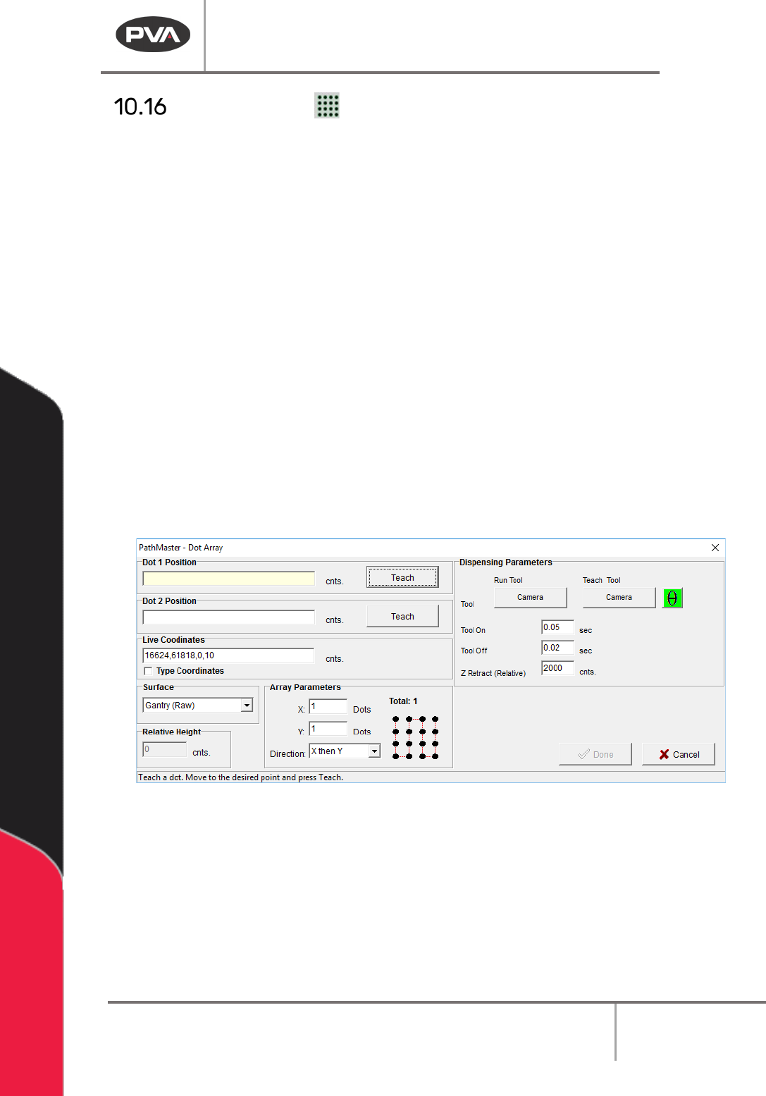
Dot Array
Select any two corners of the array to create the array. The order the dots are taught
determines the direction of the array. The program will automatically calculate the number
of dots and the row spacing based on the set values.
1. Select the Dot Array function.
2. Select the Run Tool. Select (double click) on the necessary tool from the window.
Refer to
Figure 68.
3. Select the Teach Tool if necessary. Select (double click) the necessary tool from the
Tool Selection window. Refer to
Figure 68.
4. Select “θ” to move the selected tool to the calibrated W-axis position (theta).
NOTE: The “θ” button will only be available on 4-axis machines. When you use the “Teach
Tool” (virtual tool 0) it is not necessary to select this button.
5. Select the Surface from the drop-down menu. In some units, you can set the
Relative Height.
6. Set the Tool On and Tool Off settings in seconds. Use the keyboard to type the
values.
7. Set the Z Retract (Relative) setting in counts. Use the keyboard to type the value.
Figure 113: Create Dot Array
8. Set the number of dots for the X-axis.
9. Set the number of dots for the Y-axis.
10. Set the Direction for the dot array from the drop-down menu, either “X then Y” or “Y
then X”.
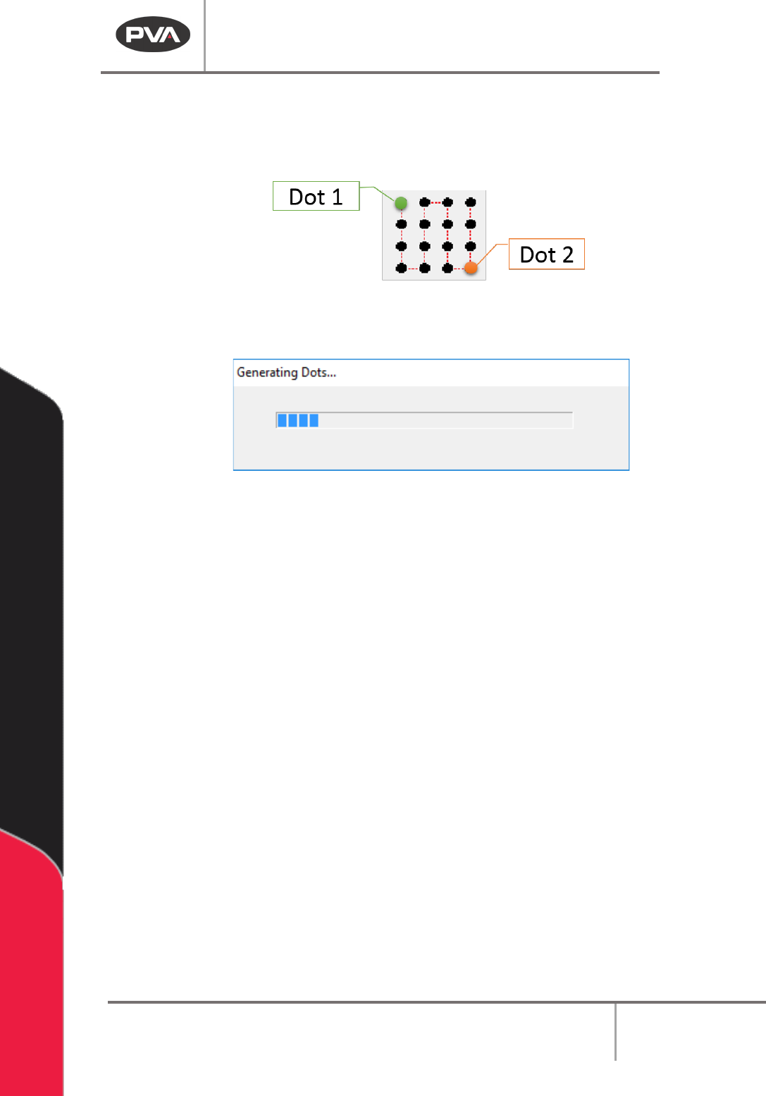
11. Teach the Dot 1 position. Move to the necessary position and select “Teach”. In the
example, this is the top left-hand corner of the array.
Machine Operation Manual
Revision L /
February 2020
Page 98 of 200
12. Teach the Dot 2 position. Move to the necessary position and select “Teach”. In the
example, this is the bottom right-hand corner of the array.
NOTE: The order you teach the dots in determines the direction of the array.
Figure 114: Dot 1 and 2
A window will show that the dots are generating.
Figure 115: Generating Dots
13. Select “Done” when you are finished.
Machine Operation Manual
Revision L /
February 2020
Page 99 of 200
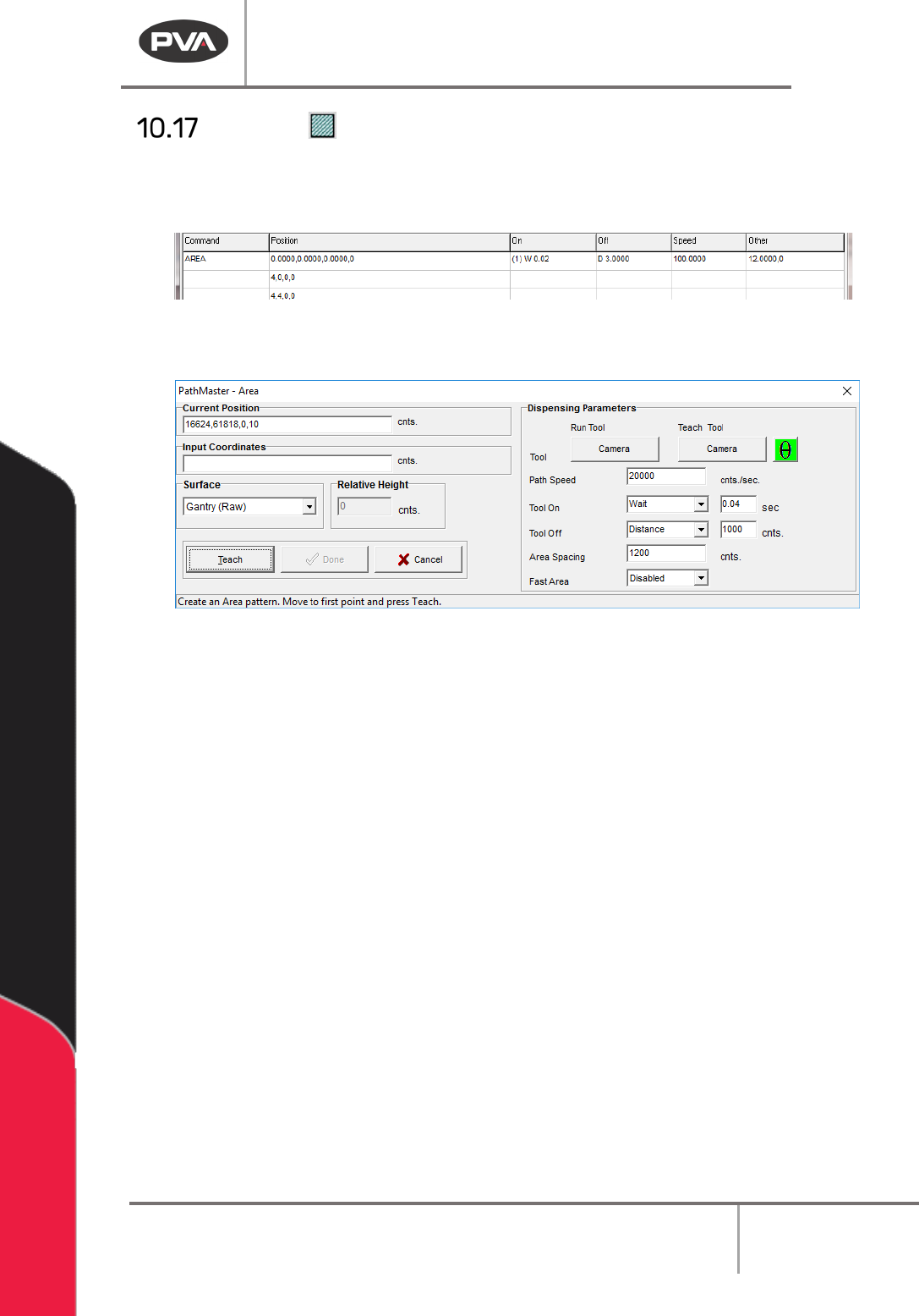
Area
This function teaches rectangular paths. The Z-axis does not alter its position during the
path. Refer to Section 10.1 for definitions of the tool functions.
Figure 116: Programmed Area Command
1. Select the Area function.
Figure 117: Teach Area
2. Select the Run Tool. Select (double click) the necessary tool from the Tool Selection
window. Refer to
Figure 68.
3. Select the Teach Tool if necessary. Select (double click) the necessary tool from the
Tool Selection window. Refer to
Figure 68.
4. Select “θ” to move the selected tool to the calibrated W-axis position (theta).
NOTE: The “θ” button will only be available on 4-axis machines. When you use the “Teach
Tool” (virtual tool 0) it is not necessary to select this button.
5. Select the Surface from the drop-down menu. In some units, you can set the
Relative Height.
6. Set the Path Speed.
7. Set the Tool On to “Wait” or “Distance” and set the time or distance in the box.
8. Set the Tool Off to “Wait” or “Distance” and set the time or distance in the box.
9. Select the three points. Include the start point and move (clockwise or counter-
clockwise) in the direction the axes must move.
10. Select “Done” to save the changes, or “Cancel” to exit and not save changes.
11. To edit an Area, double click on the path and change the command in the edit
window. Refer to Section 7.5.