PathMaster-REV-L-4.5-1.pdf - 第94页
Machine Operati on Manual Revision L / February 2020 Page 94 of 2 00 C irc le This function teaches a circle. A circle must ha ve thre e point s. The Z - axis does no t change position in th is path. Re fer to Secti on 1…
Machine Operation Manual
Revision L /
February 2020
Page 93 of 200
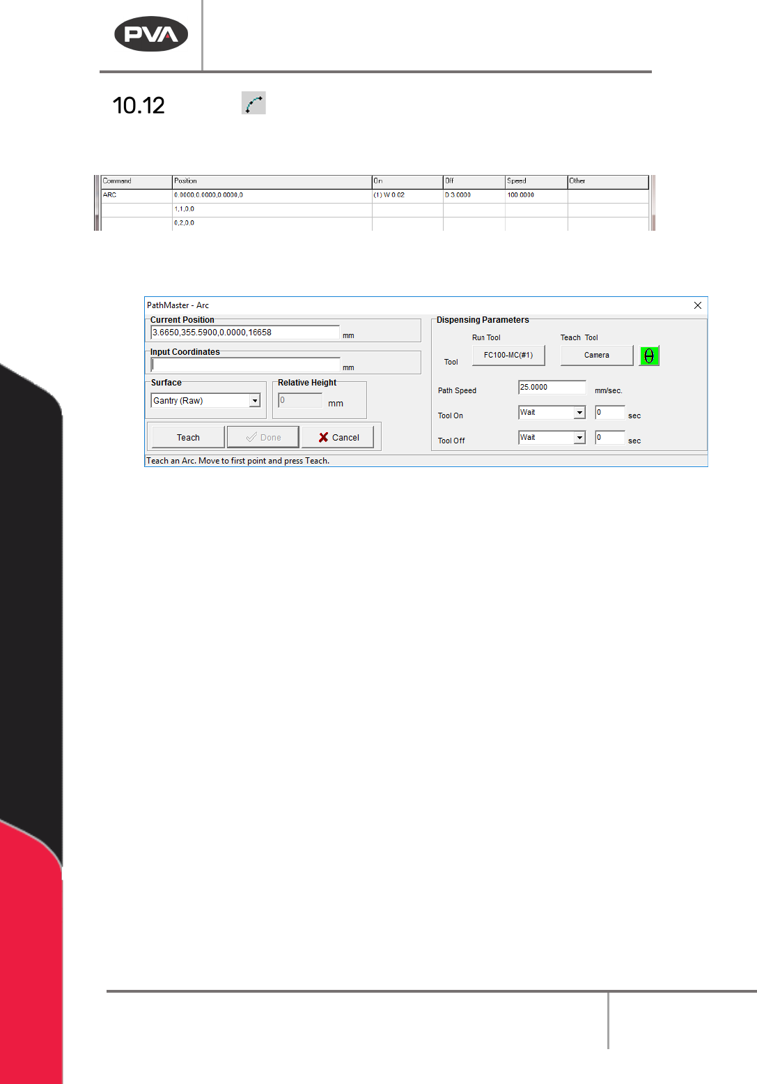
Arc
This function teaches an arc. An arc must have three points. The Z-axis does not change
its position in the path. Refer to Section 10.1 for definitions of the tool functions.
Figure 104: Programmed Arc Command
1. Select the Arc function.
Figure 105: Teach Arc
2. Select the Run Tool. Select (double click) the necessary tool from the Tool Selection
window. Refer to
Figure 68.
3. Select the Teach Tool if necessary. Select (double click) the necessary tool from the
Tool Selection window. Refer to
Figure 68.
4. Select “θ” to move the selected tool to the calibrated W-axis position (theta).
NOTE: The “θ” button will only be available on 4-axis machines. When you use the “Teach
Tool” (virtual tool 0) it is not necessary to select this button.
5. Select the Surface from the drop-down menu. In some units, you can set the
Relative Height.
6. Set the Path Speed.
7. Set the Tool On to “Wait” or “Distance” and set the time or distance in the box.
8. Set the Tool Off to “Wait” or “Distance” and set the time or distance in the box.
9. Teach the three points. Include the start point and move (clockwise or counter-
clockwise) in the direction the axes must move. Use the teach pendant or input the
coordinates.
NOTE: When you select points, space them evenly around the arc.
10. Select “Done” to save the changes, or “Cancel” to exit and not save changes.
11. To edit an Arc, double click on the path and change the command in the edit
window. Refer to Section 7.5.
Machine Operation Manual
Revision L /
February 2020
Page 94 of 200
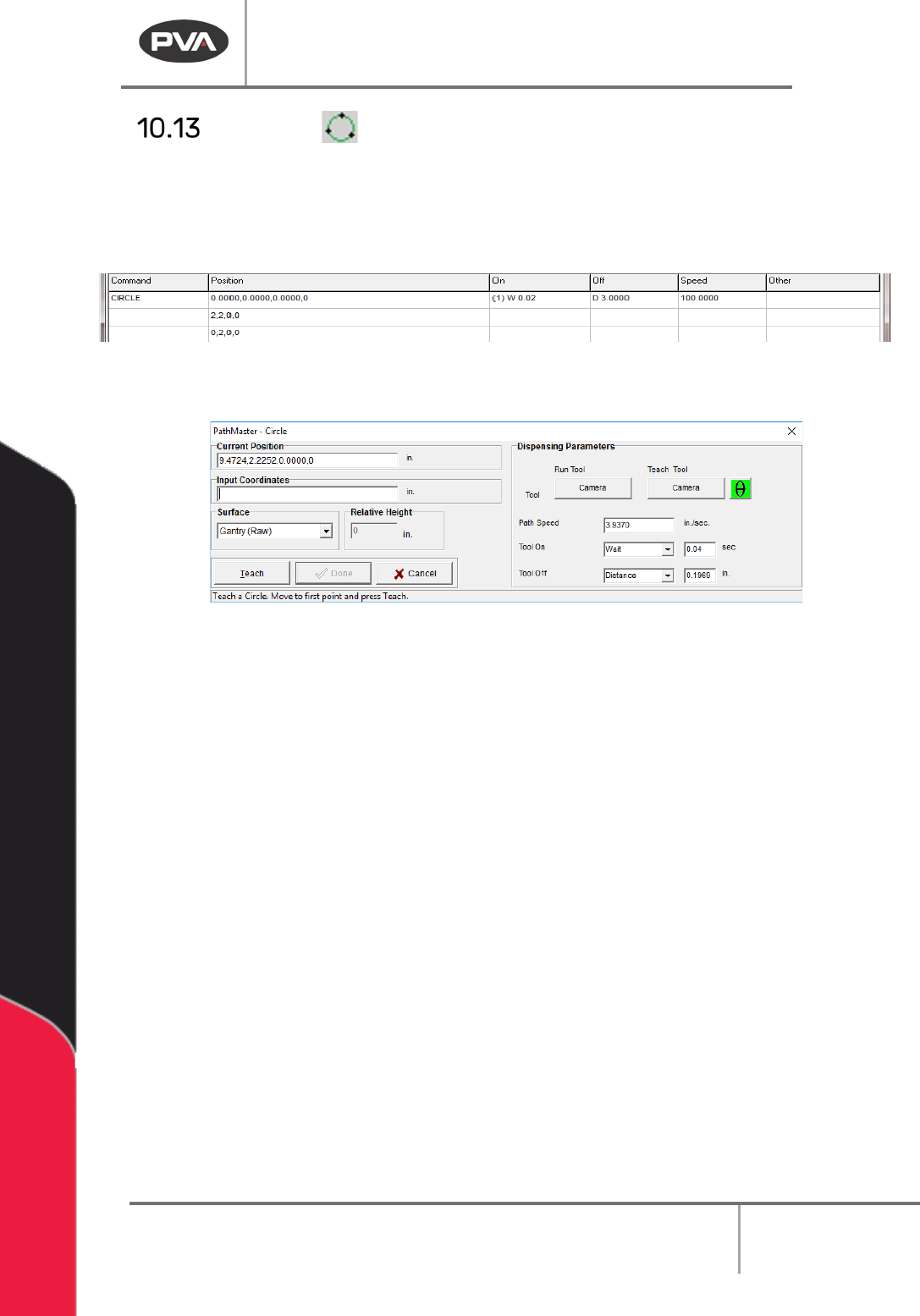
Circle
This function teaches a circle. A circle must have three points. The Z-axis does not change
position in this path. Refer to Section 10.1 for definitions of the tool functions.
NOTE: When you select points, space them evenly around the circle. Do not use the same
point for the first and last point.
Figure 106: Programmed Circle Command
1. Select the Circle function.
Figure 107: Teach Circle
2. Select the Run Tool. Select (double click) the necessary tool from the Tool Selection
window. Refer to
Figure 68.
3. Select the Teach Tool if necessary. Select (double click) the necessary tool from the
Tool Selection window. Refer to
Figure 68.
4. Select “θ” to move the selected tool to the calibrated W-axis position (theta).
NOTE: The “θ” button will only be available on 4-axis machines. When you use the “Teach
Tool” (virtual tool 0) it is not necessary to select this button.
5. Select the Surface from the drop-down menu. In some units, you can set the
Relative Height.
6. Set the Path Speed.
7. Set the Tool On to “Wait” or “Distance” and set the time or distance in the box.
8. Set the Tool Off to “Wait” or “Distance” and set the time or distance in the box.
9. Select three points on the circumference of the circle. Include the start point and
move (clockwise or counter-clockwise) in the direction the axes must move.
10. Select “Done” to save the changes, or “Cancel” to exit and not save changes.
11. To edit a circle, double click on the path and change the command in the edit
window. Refer to Section 7.5.
NOTE: You can only operate Playback if the workcell is in Manual mode.
Machine Operation Manual
Revision L /
February 2020
Page 95 of 200
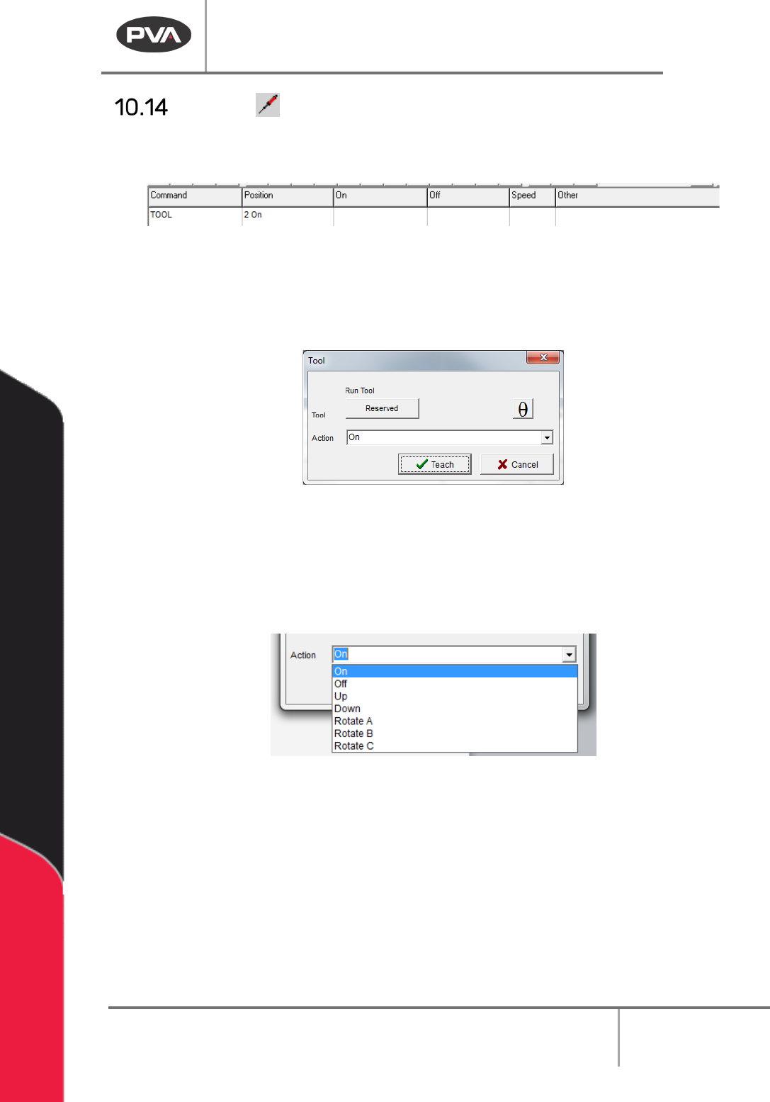
Tool
With this tool the user can enter a tool (tool) command into the edit window. Only tools that
are configured in machine parameters are shown in this window.
Figure 108: Programmed Tool Command
1. Select the Tool function.
2. Select the Run Tool.
3. Select (double click) the necessary tool from the window. Refer to Figure 68.
Figure 109: Tool Window
4. Select “θ” to move the selected tool to the calibrated W-axis position (theta).
NOTE: The “θ” button will only be available on 4-axis machines. When you use the “Teach
Tool” (virtual tool 0) it is not necessary to select this button.
5. Select the Action from the dropdown menu.
Figure 110: Tool Dropdown Menu
6. Select “Teach” to save the command, or “Cancel” to exit and not save the
command.
7. To edit a tool command, double click on the tool command in the program table to
open the Tool Command window.
Pneumatic positions (tool up/down, rotary selection) are not automatically programmed by
PathMaster®. The operator must select the correct tool in PathMaster® and put the
necessary pneumatic commands in the program after a path has been completed. Refer to
Section 10.14 for more information.