PathMaster-REV-L-4.5-1.pdf - 第64页
Machine Operati on Manual Revision L / February 2020 Page 64 of 200 Communications This feature i s used to c onfigure t he RS - 2 32 communica tion or Ethern et settin gs between the compu ter and the workcell . PathMa …
Machine Operation Manual
Revision L /
February 2020
Page 63 of 200
Auxiliary
The machine auxiliary feature is used to hardcode custom software options into the
machine software. This function is programmed by PVA and instructions on how to use it
are supplied if necessary.
1. Select
Setup->Machine Parameters
from the Main menu to open the Machine
Parameters window.
2. If necessary, select the “Machine Auxiliary” button.
Figure 62: Machine Auxiliary
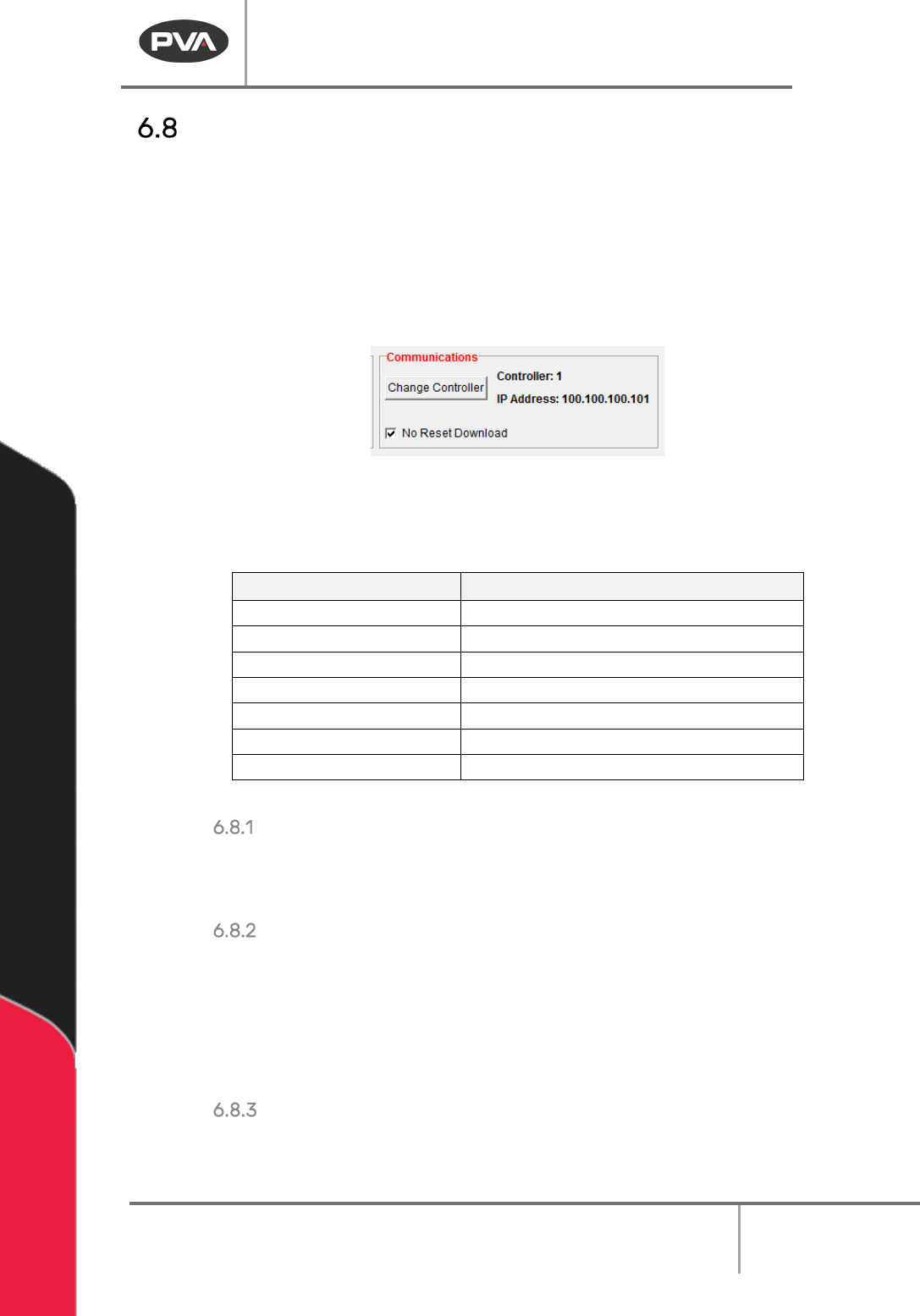
3. Make the necessary changes in the Auxiliary Code window.
Figure 63: Auxiliary Code
4. Select “Save & Close” to keep the changes.
5. Select “Cancel” to exit and not save changes.
Machine Operation Manual
Revision L /
February 2020
Page 64 of 200
Communications
This feature is used to configure the RS-232 communication or Ethernet settings between
the computer and the workcell. PathMaster® uses control handles to store all
communication settings for a machine. The information in the control handles is stored in
the Windows® registry. PathMaster® can have multiple control handles configured, but
only one control handle can be selected at a time. When PathMaster is installed it creates
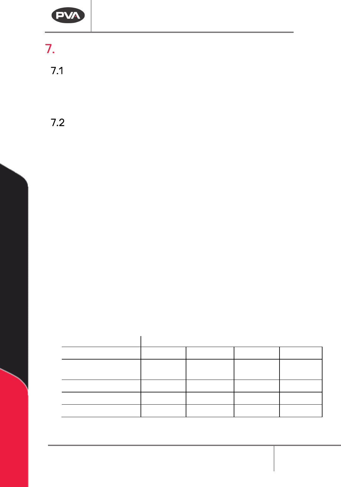
controller 1 as an Ethernet controller with an IP address of 100.100.100.101 as a default.
These settings are found in the Machine Parameters window.
Figure 64: Communications
The table below has the list of IP Addresses referenced directly by PathMaster® or its
underlying architecture.
IP Address
Description
100.100.100.101
Motion Controller 1 (Default)
100.100.100.102
Motion Controller 2
100.100.100.103
Motion Controller 3
100.100.100.104
Motion Controller 4
100.100.100.105
Motion Controller 5
100.100.100.106
Motion Controller 6
100.100.100.110*
Remote I/O
Table 4: PathMaster IP Addresses
Change Controller
Select “Change Controller” to select from any pre-configured controller handles stored in
the Windows® registry.
No Reset Download
If you select this feature the workcell will not reset when the project is downloaded. The
DMC Motion Controller must have the latest firmware revision (D220S36N or higher) to use
this feature. The main program of the machine must be programmed for this feature. If the
main program has not been changed, the workcell will show a command error. Refer to the
Troubleshooting document for more information.
Saving Machine Parameters
When all machine parameters have been set, select the “Save & Close” button to save the
parameters and return to the main PathMaster® window.
Machine Operation Manual
Revision L /
February 2020
Page 65 of 200
Program Details
Main Program Modifications
If it is sometimes necessary to make changes in the main program that runs the workcell.
You must correctly download the corrected main file to prevent any problems. Use a text
editor, such as Windows
®
Notepad or Winpad to open the
Main
program.
Common Main Program Changes
There are a few sets of points that regularly need to be changed, these include: standby
position, purge position, solvent cup position, and calibration position. In the main program
these settings are in the Machine Specific Information section (near the end of the file). An
example is shown below:
REM !!!! Machine-Specific Information !!!!
#IMACH;MT 1,1,1,1
CE 0,0,0,0;FSTX=20000;SLWX=10000;FSTY=20000;SLWY=10000
FSTZ=10000;SLWZ=5000;FSTW=10000;SLWW=5000
KNTOOL=3;A_TOOL[1]="FCS100";R_TOOL[1]=0
A_TOOL[2]="FC100 ";R_TOOL[2]=1
A_TOOL[3]="DISPSE";R_TOOL[3]=1
PT_APG[0]=80000;PT_APG[1]=65000;PT_APG[2]=0;PT_APG[3]=3000
PT_SOL[0]=80000;PT_SOL[1]=65000;PT_SOL[2]=0;PT_SOL[3]=3000
PT_CAL[0]=15000;PT_CAL[1]=15000;PT_CAL[2]=500;PT_CAL[3]=2000
PT_SBY[0]=25000;PT_SBY[1]=25000;PT_SBY[2]=250;PT_SBY[3]=3500
AP_EN=0;AP_LEN=2000;AP_TIME=30000;PNTO=4000;LT_EN=1;AC_TMR=1
SLP_TM=30000;SO_EN=0;LLA_EN=0;LLB_EN=0
#TUNE;AC*=325000;DC*=300000;SP*=120000;VA*=70000;VD*=70000
BL -4000,-4000,-1000,-1000
FL 83000,85000,15000,30000;TL*=9.9999
KD 67.99,82.43,76.09,50.00
KP 5.66,6.75,8.38,5.00
KI 0.25,0.19,0.34,0.50;EN
The following tables display the command variables that it may be necessary to change.
Table 5 – Coordinate System Locations
Axis
Locations
X
Y
Z
W
Auto Purge Location
PT_APG[0]
PT_APG[1]
PT_APG[2]
PT_APG[3
]
Solvent Cup Location
PT_SOL[0]
PT_SOL[1]
PT_SOL[2]
PT_SOL[3]
Calibration Location PT_CAL[0] PT_CAL[1] PT_CAL[2] PT_CAL[3]
Standby Location PT_SBY[0] PT_SBY[1] PT_SBY[2] PT_SBY[3]
When the main program has been changed, download the new program to the controller.
Use the PathMaster®
Download
->
Main function
.