PathMaster-REV-L-4.5-1.pdf - 第43页
Machine Operati on Manual Revision L / February 2020 Page 43 of 200 Enable Paus e If you select t his featu re a p rogram can be stopped a nd then resta rte d mid - cycle in automatic p roduc tion. T he main progra m of …
Machine Operation Manual
Revision L /
February 2020
Page 42 of 200
Teach Tool
When the Teach Tool function in PathMaster® is enabled, the first virtual tool (Tool ID 0)
will be the teach tool by default and will be related to the first Device (Device ID 0). If a
workcell does not have a teach tool, the first tool spot will be reserved. If a teach tool is
added on the workcell later, the reserved first tool will become the teach tool.
Also, when the Teach Tool is enabled, PathMaster® shows the options for the teach tool.
The box should be checked if there is a teach tool installed.
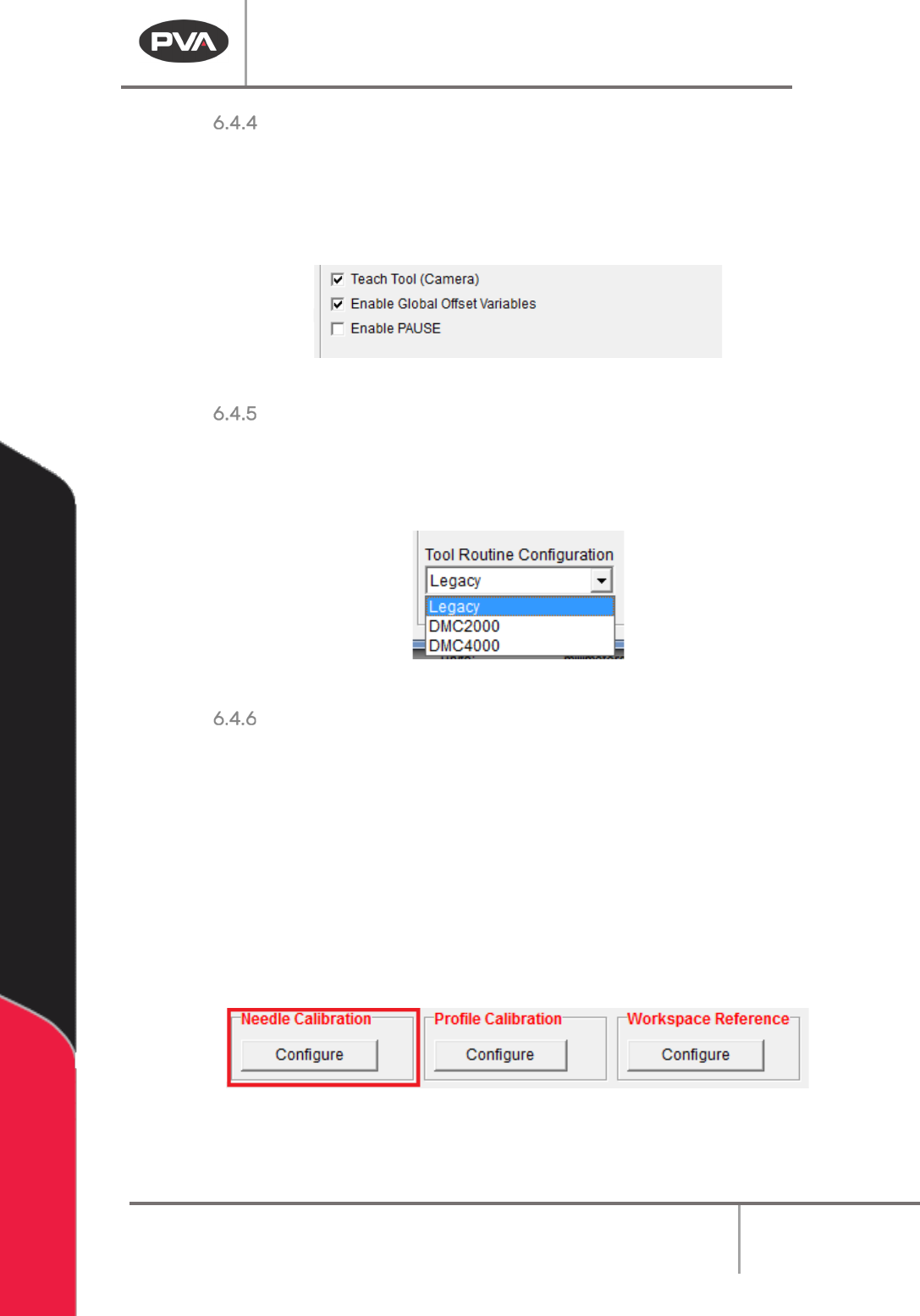
• When the Teach Tool box is selected, Pathmaster® shows the options for the teach
tool. The box should be checked if there is a teach tool installed.
Figure 31: Changes in Options When the Teach Tool Box is Selected
Some options shown in this manual are only available when the Teach Tool box is selected.
Camera Z Position
The value in the Camera Z Position box is the Z height used when the “Move to Camera Height”
function in the toolbar is selected. The machine must be in manual mode and this height should be
where the camera is in focus with the product to be observed.
Enable Global Offset Variables
If you select this feature, offset variables can be used in a workcell so that the same
program can be used in more than one workcell. The main program of the machine must be
programmed for this feature. If the main program has not been changed, the workcell will
show a Command Error (refer to the Troubleshooting manual).
Machine Operation Manual
Revision L /
February 2020
Page 43 of 200
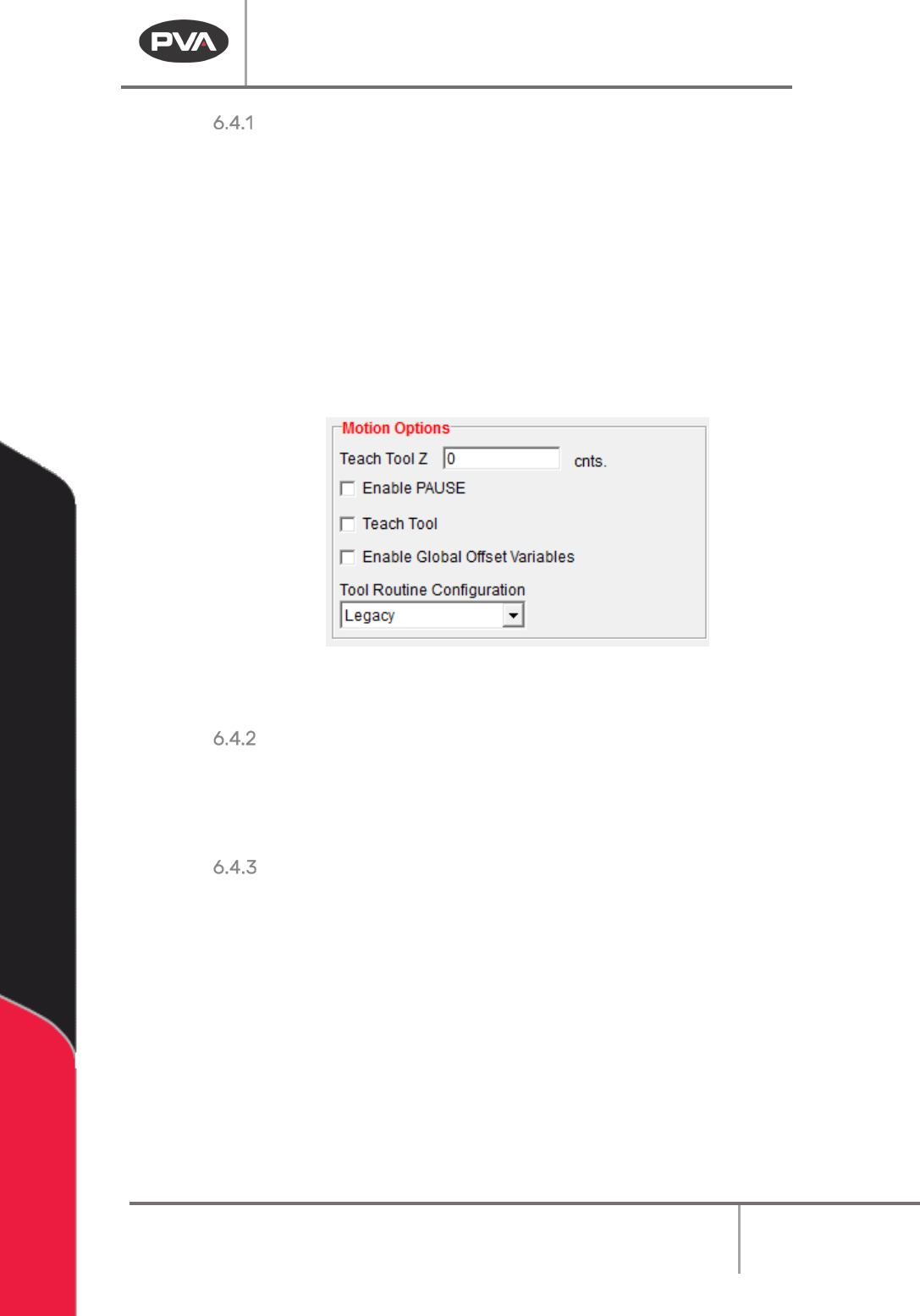
Enable Pause
If you select this feature a program can be stopped and then restarted mid-cycle in
automatic production. The main program of the machine must be programmed for this
feature. If the main program has not been changed, the workcell will show a Command
Error (refer to the Troubleshooting manual).
Figure 32: Machine Parameters, Tools Section Options
Tool Routine Configuration
The Tool Routine Configuration drop down menu will come set from the factory or will be
selected as “Legacy” if PathMaster has been updated. If you change this setting, Main
program changes will be necessary or you will have program errors.
Figure 33: Tool Routine Configuration
Needle Calibration
The Needle Calibration Reference Position defines where the needle calibration unit is
physically located in the system. The needle calibration setup is a two-part setup. First, the
needle calibration reference position is set, then, the needle calibration sensor locate
sequence runs.
WARNING: The tool offsets must be configured before the needle calibration is set up. If
Tool Offsets are not configured correctly when the Sensor Locate Sequence is run, the
system could be damaged.
1. Select the “Configure” button to set the Needle Calibration Reference position and
run the sequence.
Figure 34: Needle Calibration
2. To set the Needle Calibration Reference Position, line the teach tool up with the
cross hair on the needle calibration unit and select the “
Teach” button.
Machine Operation Manual
Revision L /
February 2020
Page 44 of 200
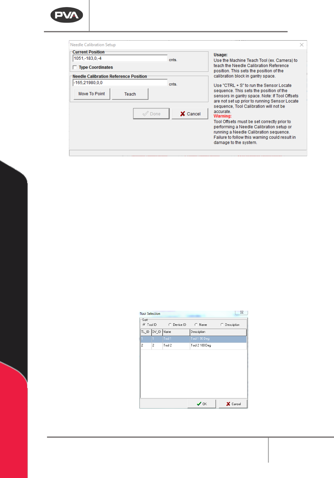
Figure 35: Needle Calibration Setup Window
3. Click the “Move To Point” button to move to the last programmed needle calibration
reference position.
4. Next, push “CTRL + S” on the keyboard to run the needle calibration Sensor Locate
sequence. It is not necessary to run this every time a needle calibration reference is
set, but it must be done initially and if the sensor is damaged or replaced. This
sequence establishes the X, Y, Z relationship of each sensor as it relates to the
crosshair on the needle calibration unit. The tool offsets and needle calibration
reference position are combined with relative sensor locations to find each tool in
the needle calibration unit.
5. Push “Ctrl + S” on the keyboard to run needle calibration Sensor Locate sequence.
6. The first time the sensor locate sequence runs, the user will be shown a list of tools.
Select the tool that will be used for the sensor locate sequence. The selection is
saved and the prompt will not be shown again.
Figure 36: Tool Selection