PathMaster-REV-L-4.5-1.pdf - 第57页
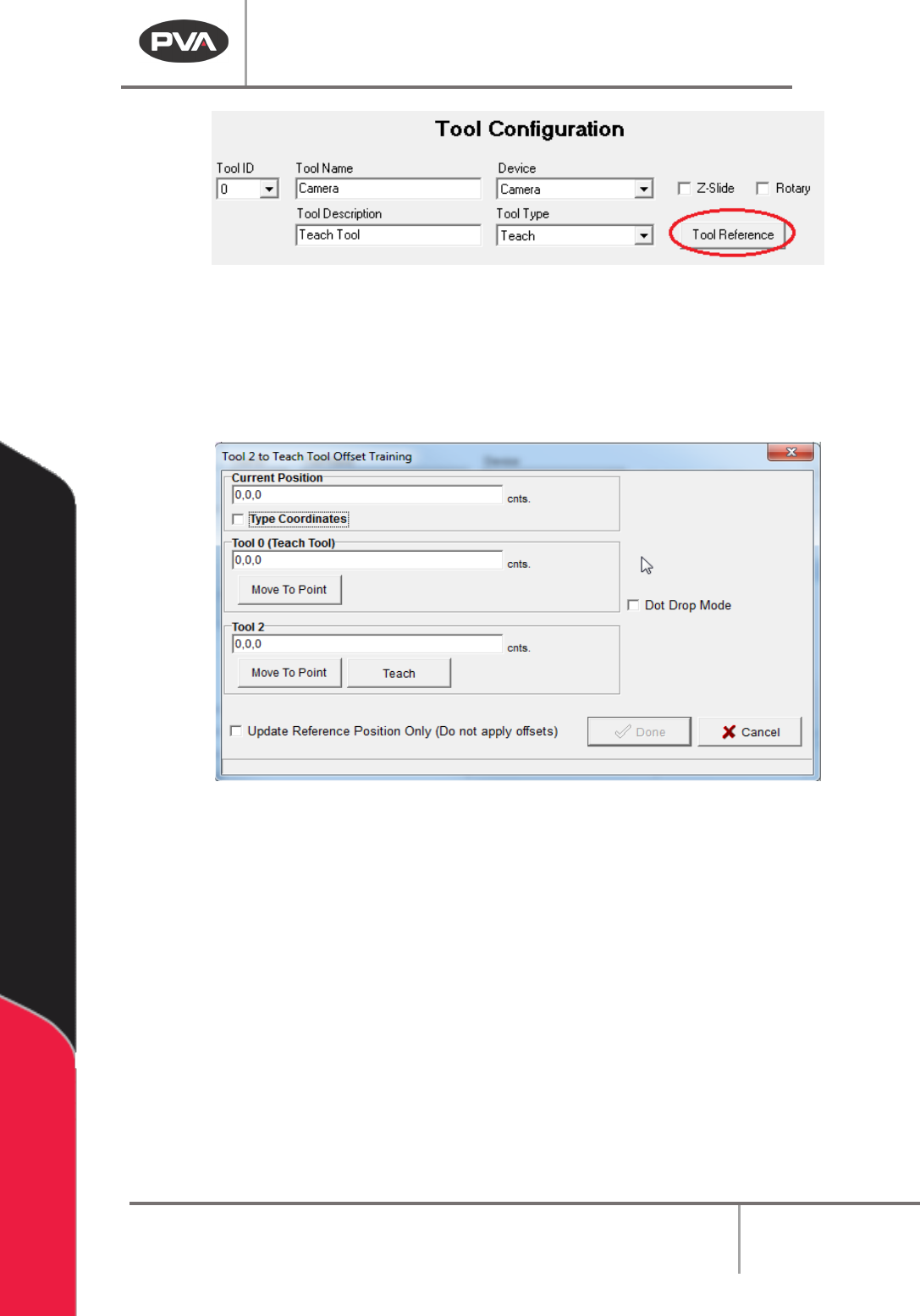
Machine Operati on Manual Revision L / February 2020 Page 57 of 200 Figure 52 : T each Too l, Tool R eference 4. Move the the ta ax is (4 - axis sy stems o nly ) to the correct posi tion wit h the T rackball or click the…
Machine Operation Manual
Revision L /
February 2020
Page 56 of 200
Tool Offsets
NOTE: Tool Offsets are only available if the Teach Tool box is checked.
Tool offsets define the X, Y, theta relationship (offset) between the teach tool (usually a
camera) and every other physical tool installed on the workcell. Tool offsets let a teach tool
be used to program paths in PathMaster® and use a different physical tool to playback the
path. PathMaster® must measure the offset for each tool relative to the teach tool for this
to work correctly. In PathMaster®, the tool offsets are defined (setup) with the Tool Offset
option in the Tool Configuration window.
When you teach tool offsets, you must put the tool in the correct state before you teach
the tool position. For example, on a 3-axis system with a dispense valve mounted on a
pneumatic rotary, put the pneumatic rotary in the necessary state (A or B). On a 4-axis
system, put the theta axis in the correct position before you teach the tool offset.
WARNING: If the Teach Tool function is enabled, the Tool Offsets must be set before the
Workspace Reference, Needle Calibration Reference, or Profile Relative Surface positions
are set. Tool Offsets also need to be set before a Tool Change, Needle Calibration, Surface
Height, or a path program is taught.
To Teach Tool Offsets
1. Select
Setup->Machine Parameters
from the Main menu to open the Machine
Parameters window.
2. Select the virtual tool you want to configure the offset for. Double click on the
virtual tool or highlight it and select “
Configure”.
NOTE: Set up the teach tool, tool 0, first. Then set up any additional tools.
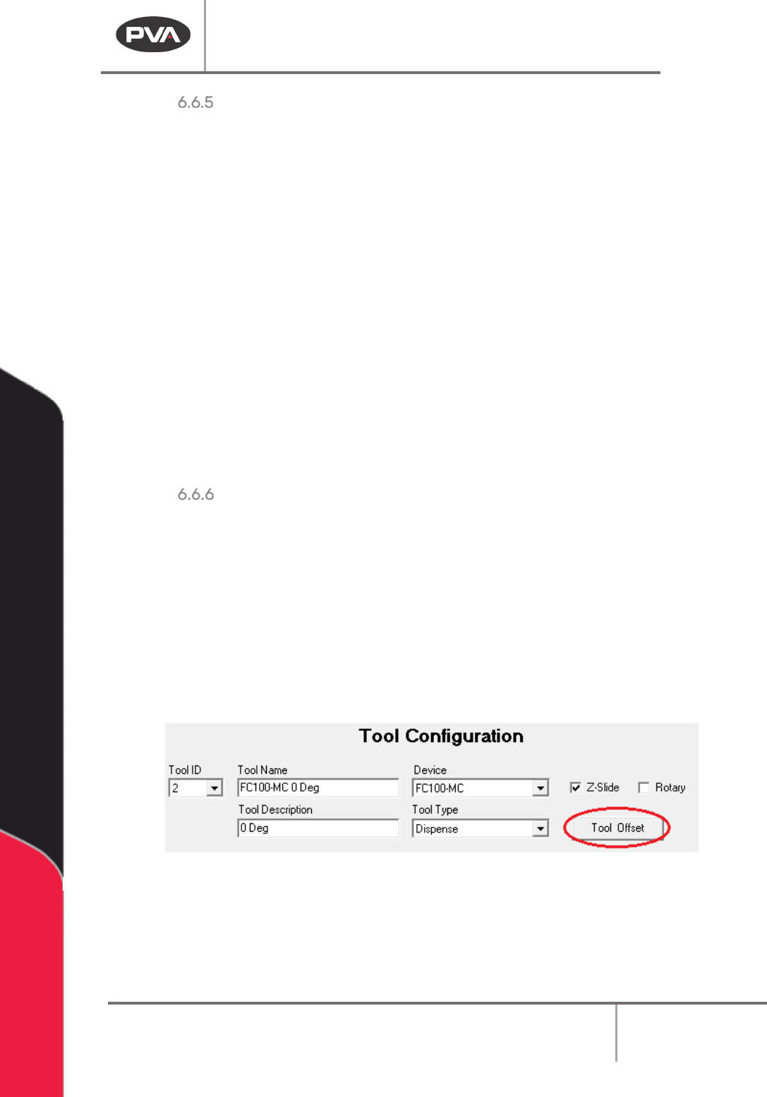
3. Select the “Tool Offset” button in the Tool Configuration window.
NOTE: If you do not have the Teach Tool (Camera) box selected in the Machine Parameters
window you will not see the “Tool Offset” button.
Figure 51: Tool Offset Button
NOTE: Tool 0 (the teach tool) has a “Tool Reference” button, not a “Tool Offset” button, and
the Tool Type is set to ‘Teach’.
Machine Operation Manual
Revision L /
February 2020
Page 57 of 200
Figure 52: Teach Tool, Tool Reference
4. Move the theta axis (4-axis systems only) to the correct position with the Trackball
or click the “θ” button to move to the last calibrated theta position.
PathMaster® must measure the offset for each tool relative to the teach tool. It is
necessary to teach a tool at a reference or fiducial point.
Figure 53: Run Tool Reference Training Window
5. Move the teach tool above the reference point, which both the teach tool and the
selected tool can reach. Or, select the “
Move to Point” button to move to the teach
tool reference point, if previously taught.
6. When the teach tool is above the reference point, select the “Teach” button. Make
sure Z height and W (optional axis) are correct in the taught position.
7. Move the run tool to the reference point and select the “Teach” button.
8. Select the Update Reference Position Only (Do not apply Offsets) checkbox to
update the reference position only, tool offsets will not be applied. The default is
unchecked, and tool offsets are applied to all corresponding path segments (all
programs, all projects).
Machine Operation Manual
Revision L /
February 2020
Page 58 of 200
NOTE: If the Update Reference Position Only (Do not apply Offsets) box is unchecked,
offsets will automatically be applied to any existing paths or programs that use the tool
that was changed and will be applied to any new paths or all programs created.
NOTE: When the Teach Tool reference position is updated, Tool Offsets are updated to
reflect the change in relationship between the Teach Tool and each Run Tool.
9. When tool offsets have been taught for each tool, select the “Done” button, or
select
“Cancel” to exit and not save changes.
The distance between the run tool and the teach tool has now been taught. Repeat steps
2-9 for all other tools.
NOTE: If the run tool is a valve, you can use a dot of material on a surface and teach the run
tool over the dot. Refer to Section 6.6.7.
10. Select the “Save & Close” button to exit and save the changes.
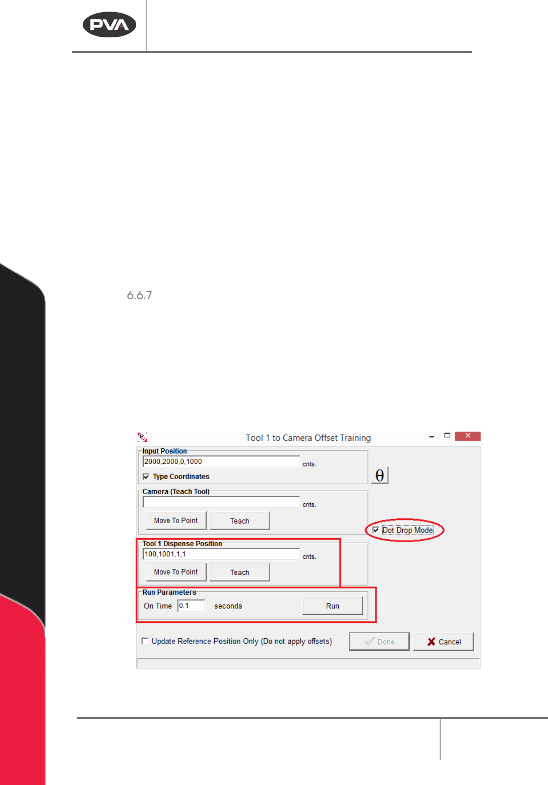
Dot Drop Mode
Dot Drop Mode is used to align the run tool and teach tool when the run tool cannot be
aligned with the reference point or fiducial because it does not have a protruding tip. It can
also be used if the operator prefers it.
1. Select the Dot Drop Mode checkbox to enable this function. When you select the
check box, the
Dispense Position and Run Parameters will be shown in the Offset
Training window. If you select and save the values for dot drop mode, the settings
will be saved for future use with this tool.
Figure 54: Dot Drop Mode