PathMaster-REV-L-4.5-1.pdf - 第193页
Machine Operati on Manual Revision L / February 2020 Page 193 of 2 00 Figure 216 : Measured Thickness 5. Enter the value in t he Part Thic kness box. Figure 217 : P art Thickn ess in mm 6. Deselect the “ Perform Check” b…
Machine Operation Manual
Revision L /
February 2020
Page 192 of 200
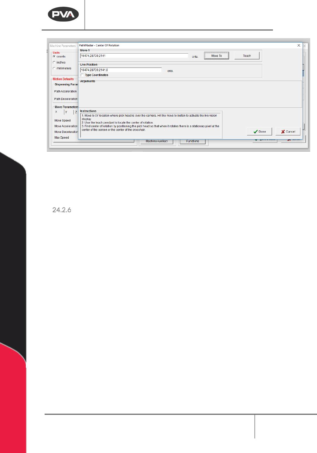
Figure 215: Center of Rotation
This will update the Galil resource associated with the center of rotation for the W-axis
relative to the camera.
4. Select the done button. The camera and light will turn off.
Part Thickness
Use the Part Measurement plugin to set the part thickness. You must do this for both the
substrate and the component.
1. In PathMaster, select
Plugins->Part Measurement
from the main menu.
2. When the Part Measurement window opens, select the “Perform Check” box.
3. Select Substrate or Component from the Operation drop down menu.
4. Highlight the section of path that has the Part Measurement plugin and run it in
manual mode.
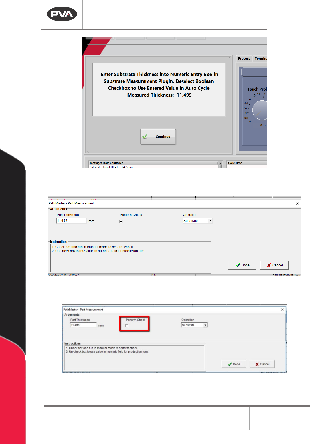
After the check is done, the Part Thickness value will be shown on the Portal screen.
Machine Operation Manual
Revision L /
February 2020
Page 193 of 200
Figure 216: Measured Thickness
5. Enter the value in the Part Thickness box.
Figure 217: Part Thickness in mm
6. Deselect the “Perform Check” box.
Figure 218: Perform Check Box

Machine Operation Manual
Revision L /
February 2020
Page 194 of 200
Path Template
After the Setup plugins for bonding are done, the next step to make a new bonding routine
is to go through the Path template and set the values for your specific parts. Refer to the
Bonding Path Template for more information.
NOTE: When possible, please use part and material values from the manufacturer.
1. Make sure the Path Template values are in the correct order with the correct values
set.
• Set part dimensions.
• Teach the part pick offset.
• Set the part thickness.
2. Highlight the section of the path that includes all of the above commands.
3. Run the highlighted section of the path.
After the you have successfully run this section of the path, continue to program the
following sections.
• Program the part inspection (Substrate). Double click on this in the Path
Template and the plugin will open.
• Program the part inspection (Component). Double click on this in the Path
Template and the plugin will open.
• Measure the Component height. Double click on this in the Path Template and
the plugin will open.
• Program the part pick. Double click on this in the Path Template and the plugin
will open.
• Program the underside dispense. This must be taught to the bare pick tool.
• Program the dog bone dispense. This must be taught to the bare datum.
• Teach the prebonding move. Double click on this in the Path Template and the
plugin will open.
When you have completed these steps continue to the Bond Manager section (24.4).