PathMaster-REV-L-4.5-1.pdf - 第133页
Machine Operati on Manual Revision L / February 2020 Page 133 of 200 How to I mport and Export Files The PathMa ster® ca n import and ex port pro gra ms, projec ts, and sub routine s. It can al so import CAD files. CAD F…
Machine Operation Manual
Revision L /
February 2020
Page 132 of 200
Password Protection
Password protection can be added to the download and save functions in PathMaster® to
prevent unauthorized or accidental changes to project files.
Download Password
Password protection can be added to the download function in PathMaster®.
1. Select
Setup -> Password -> Set Download Password
from the main menu.
If no password exists, you will be asked if you would like to create one. If a previous
password exists, you must enter it correctly to continue.
2. Enter the new password.
3. Select “OK”.
4. Enter the password again.
5. Select “OK”.
The PathMaster® Download Project and Download Main functions are now password
protected. A password will be necessary to download with these functions. If the password
is entered incorrectly, the download is canceled.
Resetting Password
1. To reset the save or download password, do the procedure to set the download or
save password.
2. Enter a new password in the new and confirm password fields.
Machine Operation Manual
Revision L /
February 2020
Page 133 of 200
How to Import and Export Files
The PathMaster® can import and export programs, projects, and subroutines. It can also
import CAD files.
CAD Files
A 2-dimensional CAD drawing can be imported into PathMaster® as a path program.
There are several steps required for a successful import. These include:
• Create the path drawing in CAD.
• Add the PathMaster® codes to the CAD drawing.
• Turn the CAD drawing to the correct position as it relates to the workcell gantry.
• Export the CAD drawing to a *.dxf (Autodesk Drawing Exchange Format).
• Import the CAD drawing into PathMaster® with the CAD wizard.
• Prepare the CAD File.
NOTE: The CAD X+ and CAD Y+ arrows are for reference only and are not necessary.
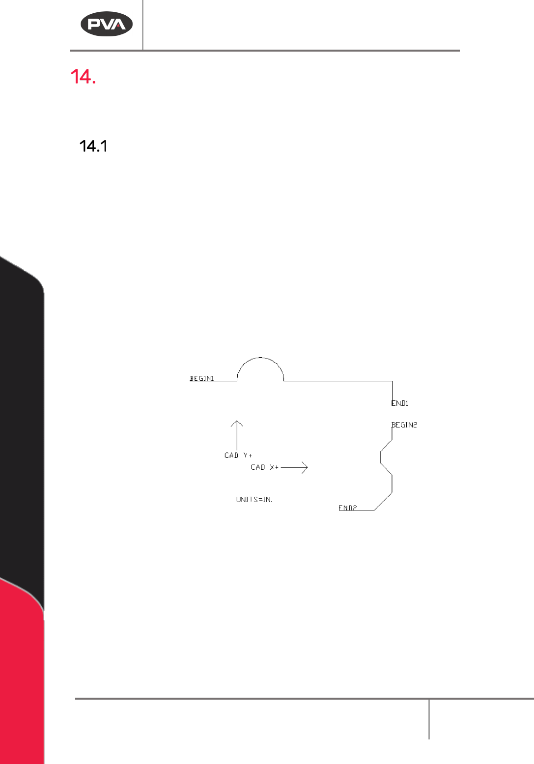
Figure 165: Original CAD Image
1. The start and end of each segment must be labeled as shown in the image above
and as described in the table below.
2. Put the units in the CAD drawing as shown.
Machine Operation Manual
Revision L /
February 2020
Page 134 of 200
Required Element
Description
BEGIN1, BEGIN2, etc.
Defines the start of the segment. The tool will turn ON at this
point.
END1, END2, etc.
Defines the end of the segment. The tool will turn OFF at this
point.
UNITS=IN.
UNITS=MM.
UNITS=CNTS.
Defines the units used for creating the drawing.
NOTE: The path will be converted automatically to the units specified in PathMaster® when
it is imported.
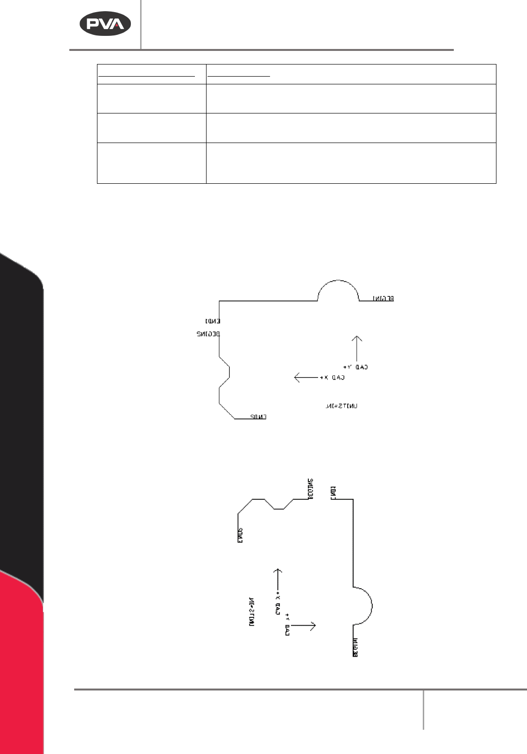
3. After all necessary elements have been put in the drawing it must be mirrored on
the Y axis.
NOTE: In AutoCAD be sure to “Delete Old Objects” when prompted.
Figure 166: CAD Drawing Mirrored on the Y Axis
4. Rotate the drawing clockwise 90° (-90° for standard AutoCAD Setup).
Figure 167: Rotate the CAD Drawing 90°