PathMaster-REV-L-4.5-1.pdf - 第126页
Machine Operati on Manual Revision L / February 2020 Page 126 of 200 2. Select the Ax es boxe s you want the s moothi ng to be a pplied to. If an a xis is not checked, no smoothing change will be ap plied to that axis . …
Machine Operation Manual
Revision L /
February 2020
Page 125 of 200
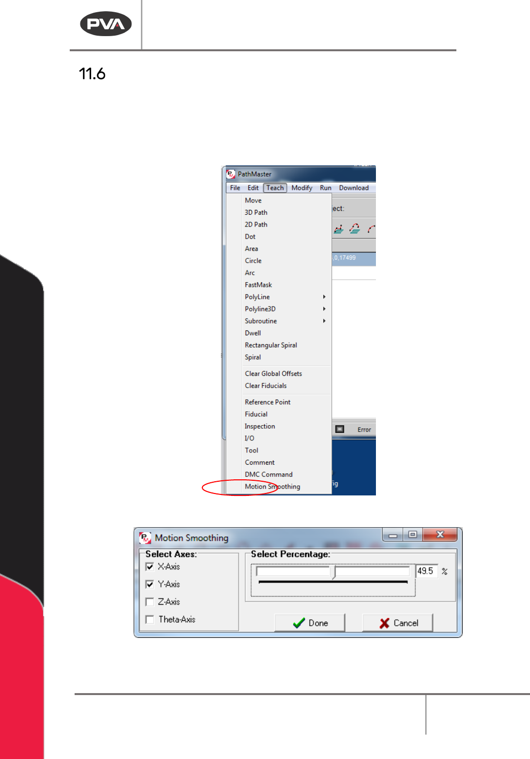
Motion Smoothing
The motion smoothing command is a jerk limiting function applied to independent and
vector motion profiles. You must have a DMC4000 or DMC 4200 series motion controller to
use this function.
1. Select the Motion Smoothing function from the Teach menu.
Figure 153: Motion Smoothing
Figure 154: Motion Smoothing Window
Machine Operation Manual
Revision L /
February 2020
Page 126 of 200
2. Select the Axes boxes you want the smoothing to be applied to. If an axis is not
checked, no smoothing change will be applied to that axis.
3. Select a percentage of smoothing within the configured range in the motion
smoothing interface window. The smoothing percentage is applied to all axes with
checked boxes.
4. Create multiple smoothing commands to use different smoothing values for
different axes.
5. When a smoothing function is used, it is applied to all motion that follows in that
path program or until another smoothing command is applied. Smoothing is reset at
the beginning of every path by default.
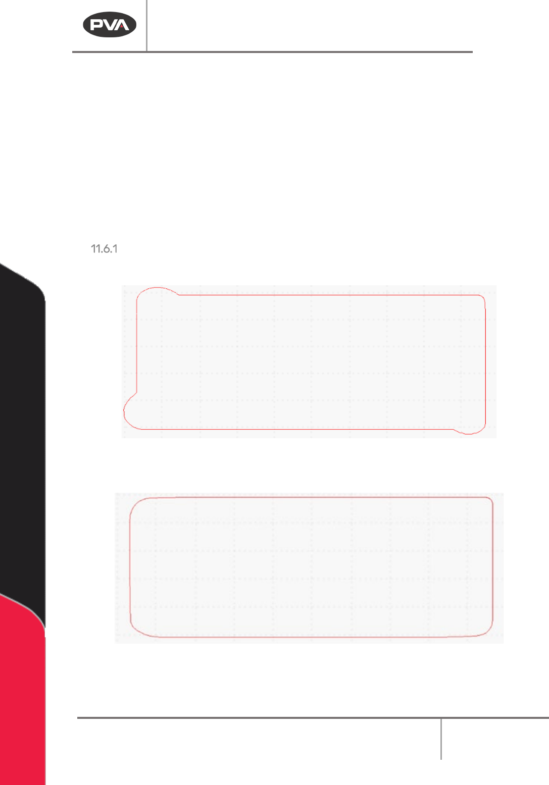
Smoothing Examples:
No Smoothing applied can cause overshooting on corners.
Figure 155: No Smoothing Applied
Smoothing applied minimizes the following error on corners.
Figure 156: Smoothing Applied
Machine Operation Manual
Revision L /
February 2020
Page 127 of 200
Offline Programming with FastPath
Before you use FastPath™, tool offsets must be configured. Refer to Section 6.6.5 for more
information.
When you are in FastPath your cursor is a crosshair. Each time a point is taught the
crosshair will briefly change to an arrow pointer to show that the point was taught.
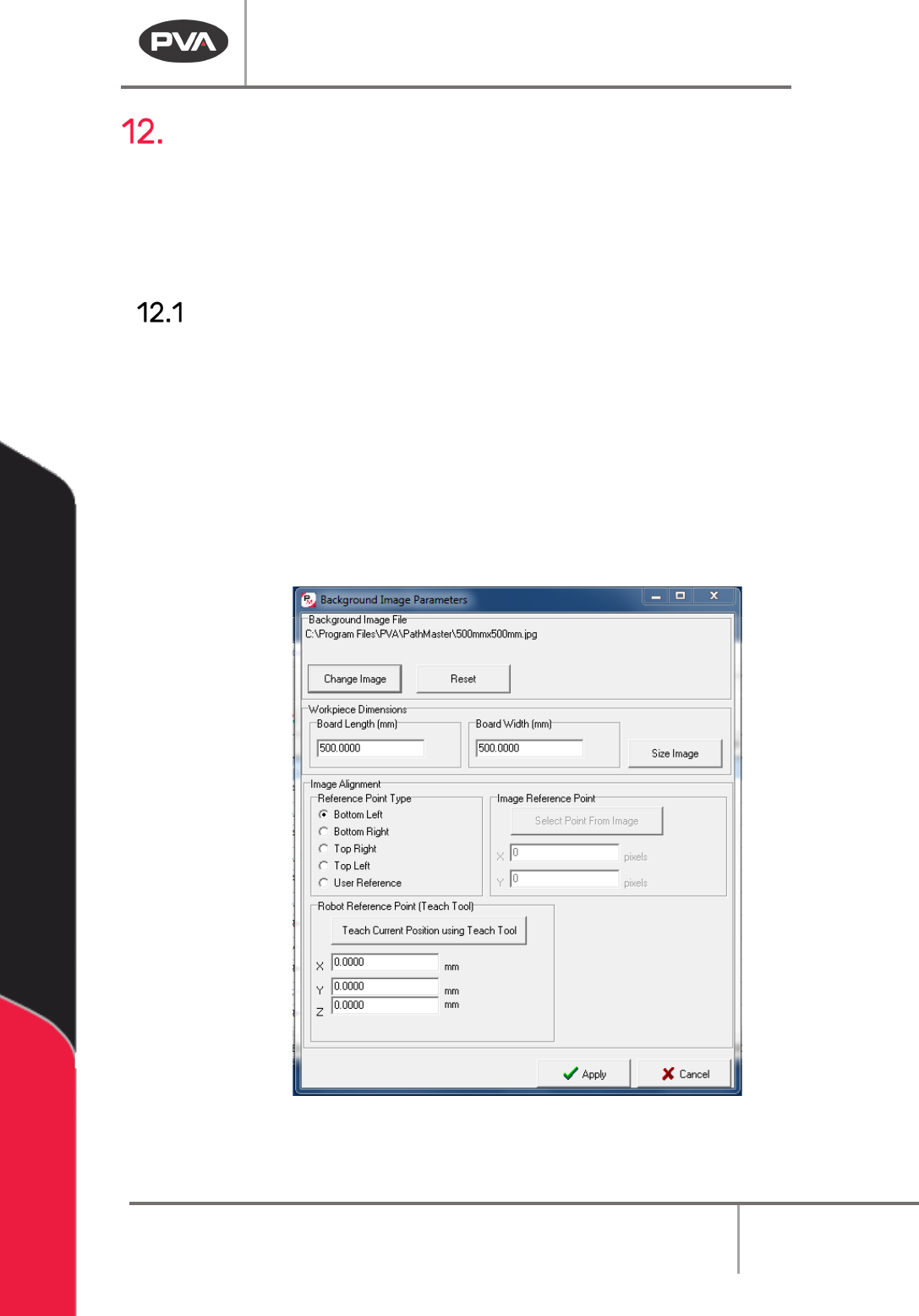
Set Up a Background Image
1. Open a new program.
2. Select
Edit->Program->Offline Image
from the main menu.
3. Select “Change Image” to change the background image. If no image is selected, the
default image will be used. The default image is a 500mm by 500mm image with a
workspace of the same size. The background image must be of a known size,
approximately the same size as the area to be dispensed upon.
4. Put the correct values in the Workpiece Dimensions boxes for Board Length and
Board Width.
Figure 157: Background Image
5. Select “Size Image”.