PathMaster-REV-L-4.5-1.pdf - 第21页
Machine Operati on Manual Revision L / February 2020 Page 21 of 200 Tool Co mmand s in Pro gra ms Pneumati c positio ns (too l up, tool dow n, rotary selection, e tc.) are no t automati cally progra mmed by Path Maste r®…
Machine Operation Manual
Revision L /
February 2020
Page 20 of 200
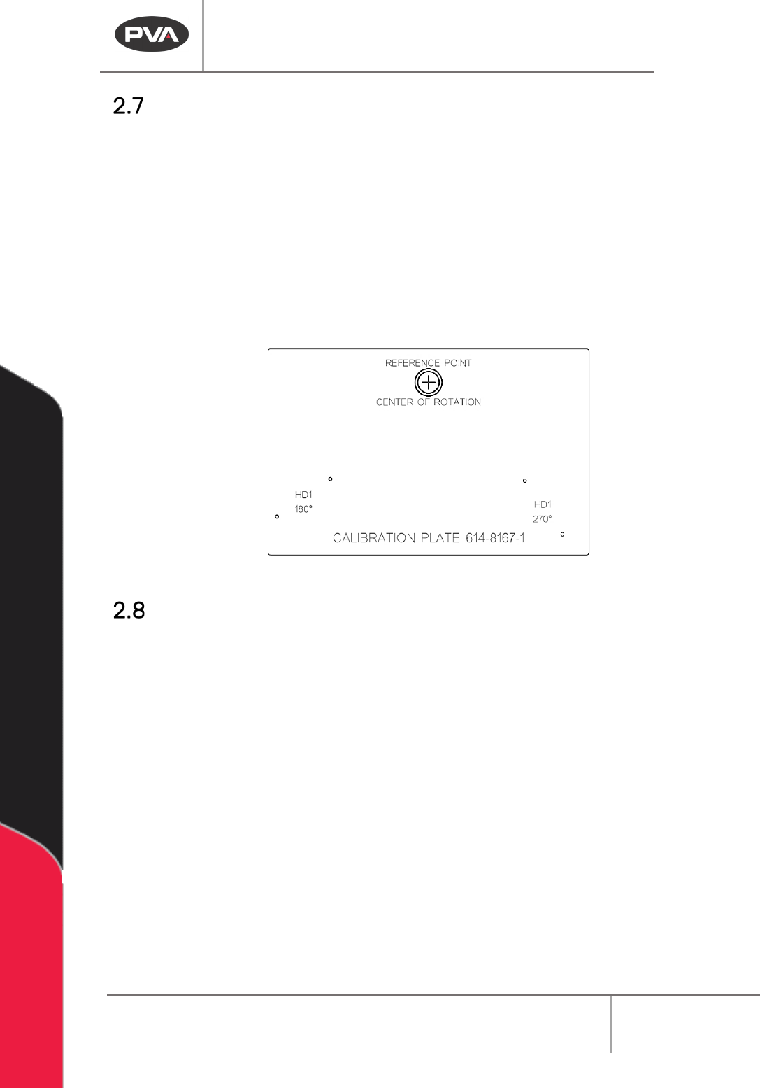
Calibration Plate
Every system should have a recognizable workspace reference position. Standard systems,
with conveyors or flex fixtures, use a calibration plate (see below). Custom systems and
systems with non-standard part fixtures will have a defined workspace reference position,
but may or may not use the standard calibration plate.
• To use the standard calibration plate, put the plate on the conveyor or flex fixture so
it is against the fixed rail and the hard stop or board stop.
• The purpose of the calibration plate, as it relates to PathMaster® 4.2 and 4.3, is to
define a consistent workspace reference position. This is very important to the
efficacy of machine transportability.
Figure 4: Calibration Plate
Path Program Planning Tips
• Look at the workpiece to be programmed and find a place to start the path.
• Plan the path program on paper with a diagram or plotted points.
• Select the tool (dispense valve, spray valve, jet) for each path.
NOTE: The first point and direction may not be best and it may be necessary to program
the path again.
• Include the active tool operations for each path, ex: Rotate A/B, Tool Up/Down.
• Put the workpiece in the workcell in a repeatable location and make sure it is parallel
with the gantry.
• Insert comments into the program for future editing or other users. Comments are
shown in red text.
NOTE: If a stop or dwell must be added at one of the points after a path is completed, the
path must be broken into two paths or be programmed again.

Machine Operation Manual
Revision L /
February 2020
Page 21 of 200
Tool Commands in Programs
Pneumatic positions (tool up, tool down, rotary selection, etc.) are not automatically
programmed by PathMaster® and there is no communication between the workcell and
PathMaster® related to the active tool and its pneumatic position. The operator must
select the correct tool in PathMaster® and put the necessary pneumatic commands in the
program. The pneumatics can be operated from the Tools Tab in Portal, or from the OIT
Interface on the workcell in Manual mode. It is important these commands are in the
correct locations. In general, follow these rules:
• Move the X and Y (and W) axes into position before a tool slide or tool rotary is
actuated.
• Actuate a tool slide before a tool rotary, if necessary. Make sure there is nothing in
the motion radius of the tool rotary.
• Program each segment with the related tool slide in the down position.
• Add tool slide down and tool rotary B commands into the path program, before any
segment(s) where the tool is used.
• Move the gantry to a save Z-height before returning a tool to rotary A position, then
actuate the tool slide. Input tool rotary A and tool slide up commands into the path
program when finished with the tool.
• To change the tool being used safely, include a non-dispense move on the Z-axis to
0, so there is room for the new tool to lower (refer to Section 2.10).
Inter-Path Movement
After a path is complete, the workcell returns to the ‘standby’ position taught in Setup
mode. It is necessary to plan out a path programs to make sure there are no obstructions
between paths. To avoid any potential crashes, program a ‘Z only’ move, with the Z-axis
target set to 0. The operator must make sure all path programs are safe to run on the
workcell and dispense surface.
Machine Operation Manual
Revision L /
February 2020
Page 22 of 200
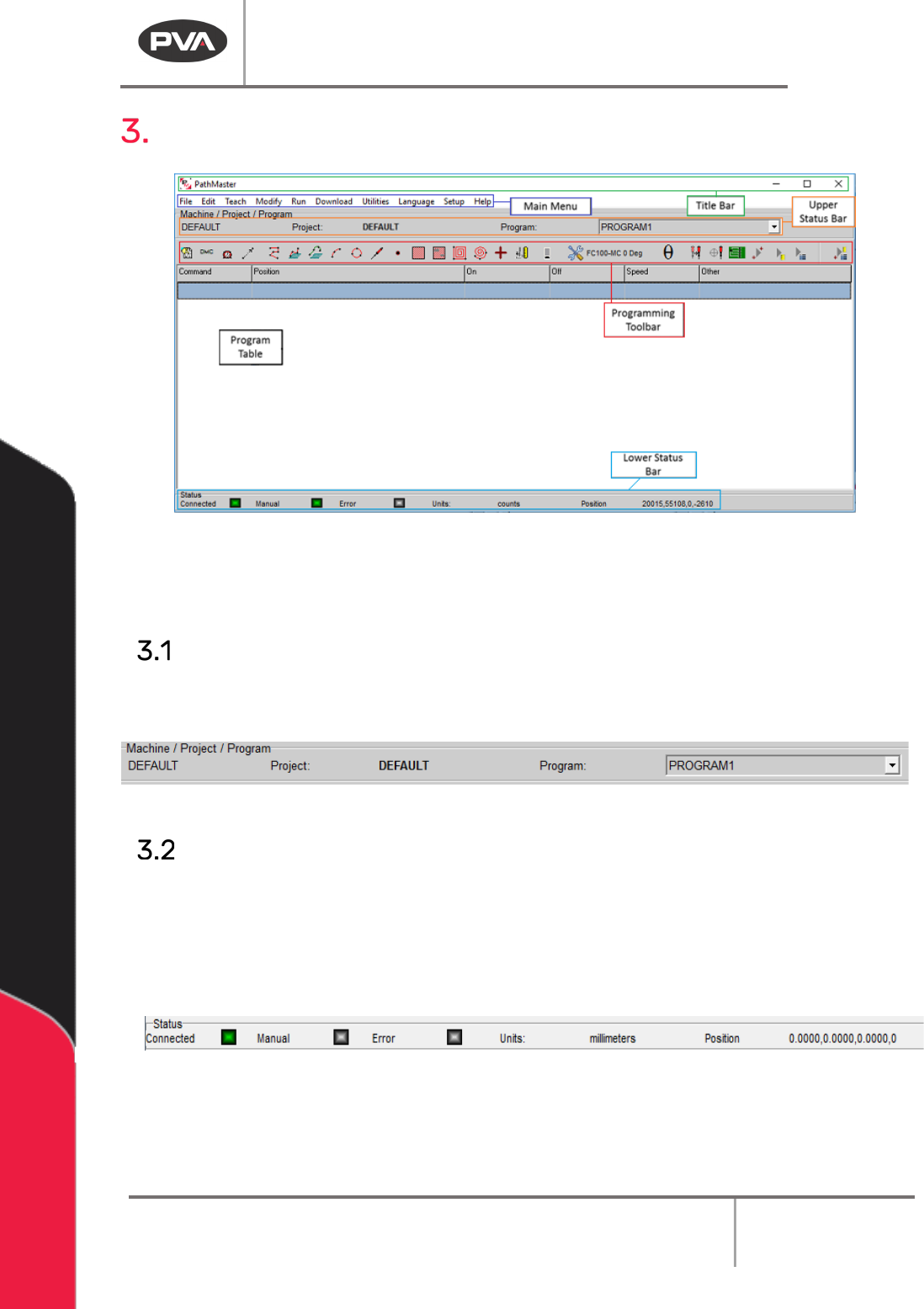
Overview
Figure 5: PathMaster® Window
If PathMaster® is opened while Portal is in use, the PathMaster® window will open as an
attached split screen below the Portal window, which will hide the Title Bar.
Upper Status Bar
The upper status bar displays the active machine configuration, current project file and
current path program, which can be changed with the Program drop-down menu.
Figure 6: Upper Status Bar
Lower Status Bar
The lower status bar shows the current status of the workcell. The communication status
between the PC and the workcell is shown in the “Connected” display. The “Manual” display
shows if the workcell is in Manual mode. The “Error” display shows if the workcell is in a
state of error. The Units field gives the measurement system used when programming
paths, and can be changed in the Setup section of PathMaster®.
Figure 7: Lower Status Bar
NOTE: In order to teach path programs online, PathMaster® must be connected to a
workcell that is in Manual mode, and not in a state of error.