PathMaster-REV-L-4.5-1.pdf - 第80页
Machine Operati on Manual Revision L / February 2020 Page 80 of 200 D well Set a dela y in program e xecution i n between p ath segme nts with the Dwel l function . 1. Select the D well functi on. 2. Put the corre ct val…
Machine Operation Manual
Revision L /
February 2020
Page 79 of 200
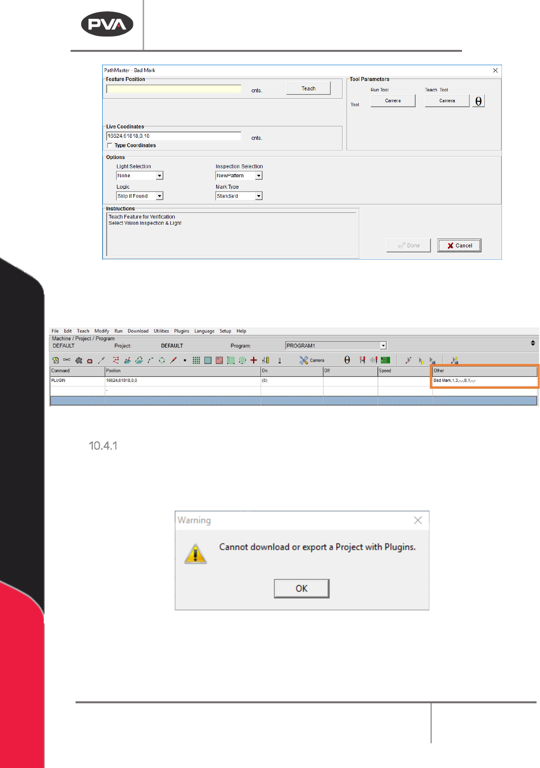
Figure 82: Example Plugin Window
Plugins will be shown on the program table with the Command as “PLUGIN” and the plugin
specific name shown in the
Other column.
Figure 83: Example Programming
Plugin Download Error
Plugins are not available to projects that are downloaded to the controller. Portal
PartManager must be used to select programs if plugins are used. If an attempt is made to
download or export a Project that contains plugins, an error will be shown.
Figure 84: Plugin Warning
Machine Operation Manual
Revision L /
February 2020
Page 80 of 200
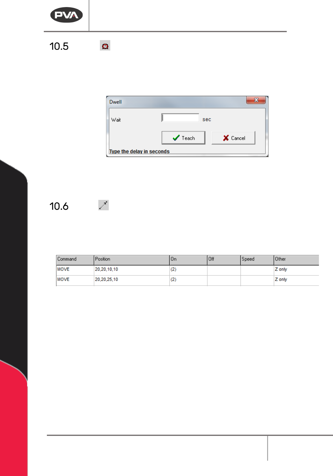
Dwell
Set a delay in program execution in between path segments with the Dwell function.
1. Select the Dwell function.
2. Put the correct value in the Wait box.
Figure 85: Teach Dwell
3. Select “Teach” to add the command to the edit screen.
4. Select “Cancel” to exit and not add a command.
Move
The Move command is a non-dispense move. The approach type is applied globally to all
points taught within a single move command and determined by the selected approach
type when the “
Done” button is clicked. If more than one approach type is necessary, teach
multiple move commands. Refer to Section
10.1 for definitions of the tool functions.
Figure 86: Move Command in the Edit Screen
1. Select the Move function.
Machine Operation Manual
Revision L /
February 2020
Page 81 of 200
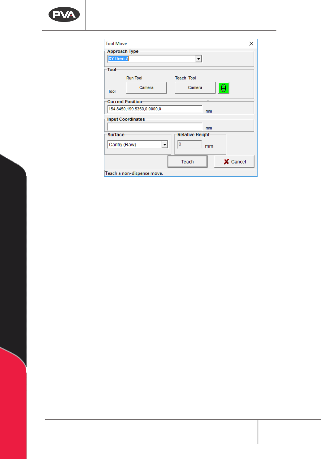
Figure 87: Tool Move
2. Select the Approach Type.
3. Select the Run Tool. Select (double click) the necessary tool from the Tool Selection
window.
4. Select the Teach Tool if necessary. Select (double click) the necessary tool from the
Tool Selection window.
5. Select “θ” to move the selected tool to the calibrated W-axis position (theta).
NOTE: The “θ” button will only be available on 4-axis machines. When you use the “Teach
Tool” (virtual tool 0) it is not necessary to select this button.
6. Select the Surface from the drop-down menu. Gantry (Raw) uses the current Z
height, Calibrated Z uses the calibrated Z height, Gantry (Relative) the user to sets a
move in Z axis relative to the taught position (mostly used for knit-line finishing).
7. Use the teach pendant or input the commands in the Input Coordinates box and
select “
Teach”.
8. Click “Teach” at the next move point as necessary.
9. Select “Done” to close the window.
10. To edit a Move command, double click on the path and change the command in the
edit window. Refer to Section 7.5.