PathMaster-REV-L-4.5-1.pdf - 第112页
Machine Operati on Manual Revision L / February 2020 Page 112 of 20 0 R elative Height The Rela tive Heigh t is shown in Pat hMaste r’s Tool Configurati on windo w ( Figure 134 ). This value must be cor rectly set or the…
Machine Operation Manual
Revision L /
February 2020
Page 111 of 200
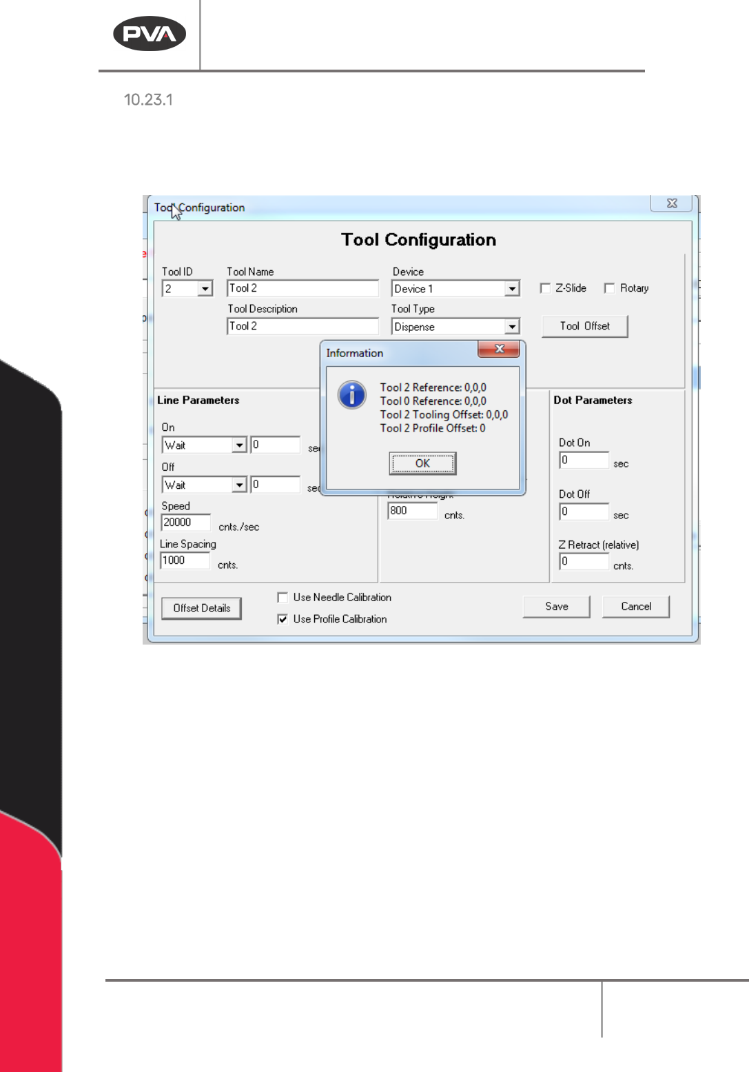
Offset Details
The offset height is shown in PathMaster’s Tool Configuration window and set in the
Camera Offset Training window. Refer to Section 6.6.5 for more information.
• Select the Offset Details button to be shown the related tool offset.
Figure 133: Example Tool Offset
Run Tool Reference – This is the absolute position where the Run Tool is positioned to
calculate the tool offset.
Teach Tool Reference – This is the absolute position where the Teach Tool is positioned to
calculate the Tool Offset.
Run Tooling Offsets – This is the difference in position between the Teach Tool and the Run
Tool (Tool Offset).
Tool Profile Offset – This is the difference between the Profile Z Common reference and
the tip of the Run Tool (Profile Offset).
Machine Operation Manual
Revision L /
February 2020
Page 112 of 200
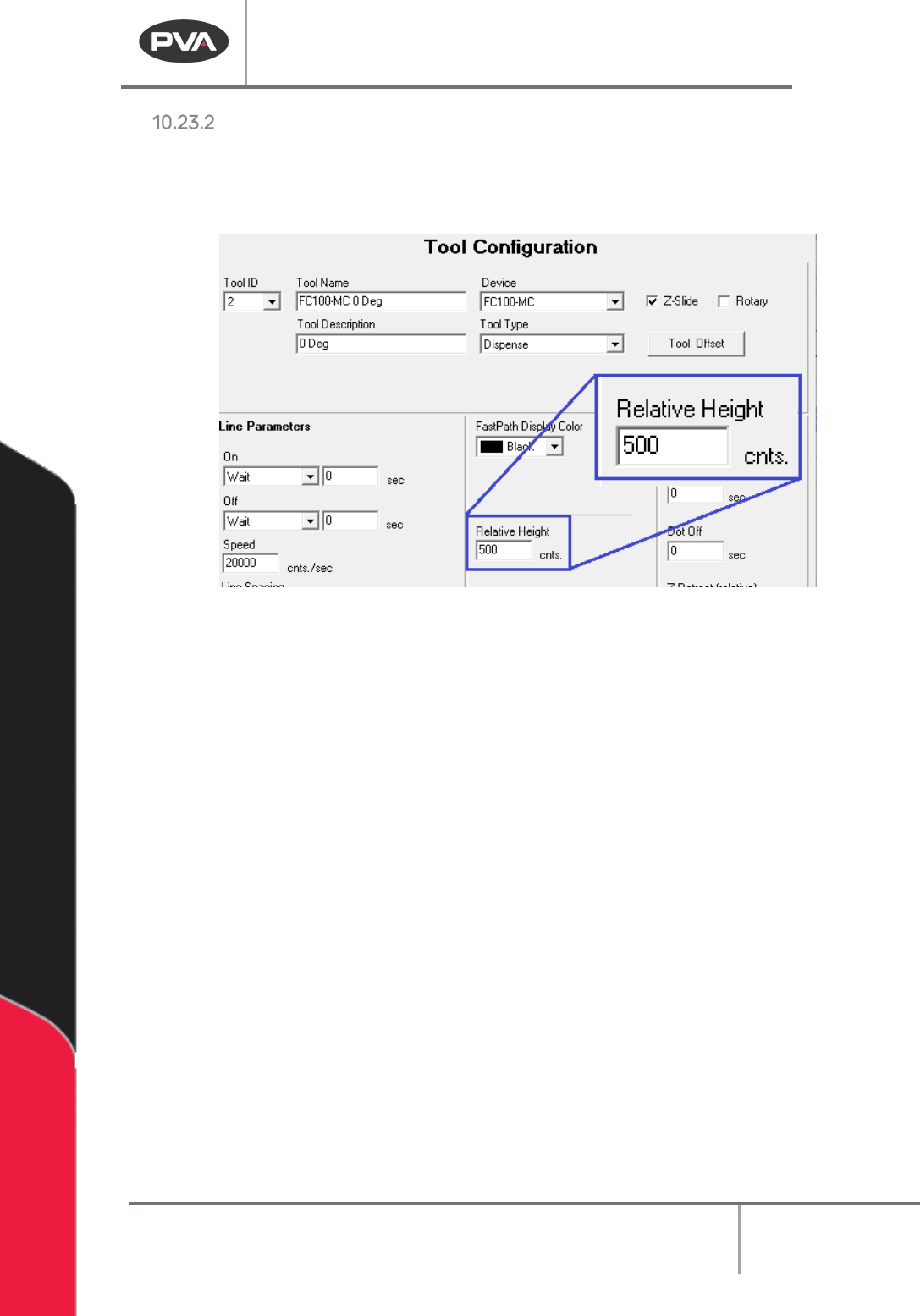
Relative Height
The Relative Height is shown in PathMaster’s Tool Configuration window (Figure 134). This
value must be correctly set or the workpiece or workcell could be damaged. This value can
be found in
Setup -> Machine Parameters -> Tool Parameters
for each tool.
Figure 134: Relative Height Input Box
Machine Operation Manual
Revision L /
February 2020
Page 113 of 200
Calibrated Z Height
The following functions have the ability to make use of “Calibrated Z Height” or the Surface
menu options Gantry (Raw), Calibrated Z, and Custom Surface:
•
Tool Move
• 2D Line
• 3D Line
• Arc
• Circle
•
Dot
• Reference Point
• PolyLine
• PolyLine3D
•
Spiral
• Rectangular
Spiral
• Area
• FastMask
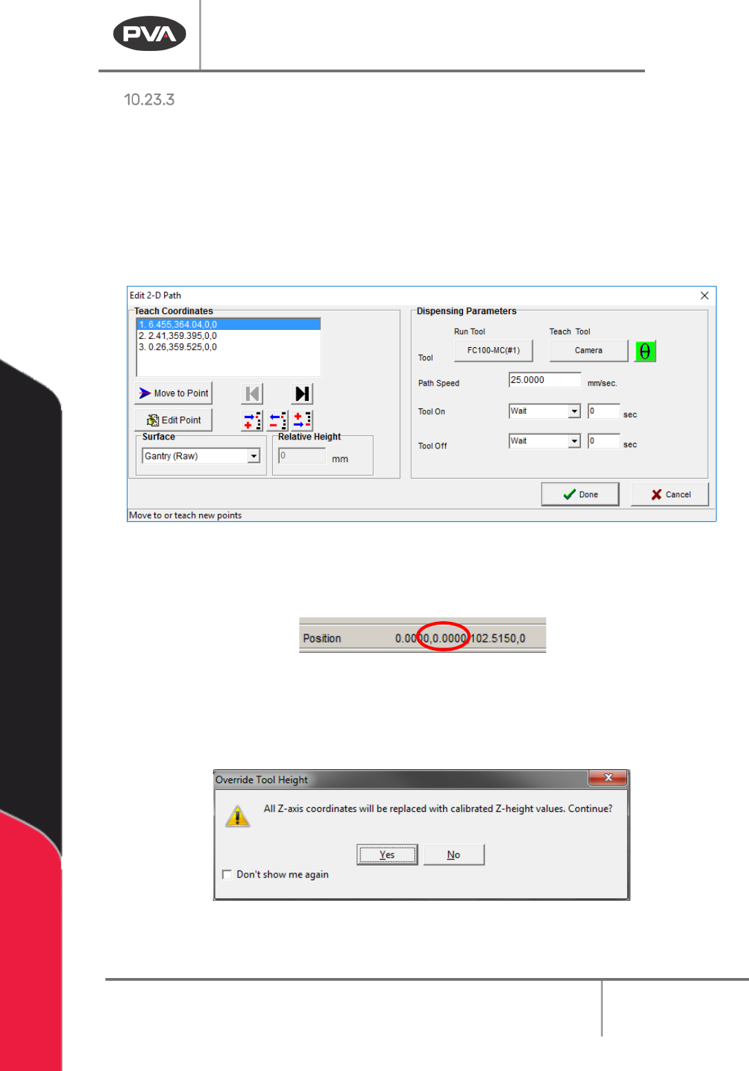
Figure 135: 2D Path with Tool Height
• When “Use Current Z Height” is selected and a point is taught, the Z-axis coordinate
used is the current Z coordinate of the machine, as shown in the Lower Status Bar.
Figure 136: Z-Axis Coordinate in the Lower Status Bar
• When “Use Calibrated Z Height” is selected and a point is taught, the saved Z-axis
coordinate is the selected tool’s calculated tool height. When a user selects “
Use
Calibrated Z Height,” the following message is shown:
Figure 137: Override Tool Height