PathMaster-REV-L-4.5-1.pdf - 第39页
Machine Operati on Manual Revision L / February 2020 Page 39 of 200 Move Para meters The move para meter s are the de fault parame te rs for all inde pende nt path moti on for ea ch axis of motion that doe s not include …
Machine Operation Manual
Revision L /
February 2020
Page 38 of 200
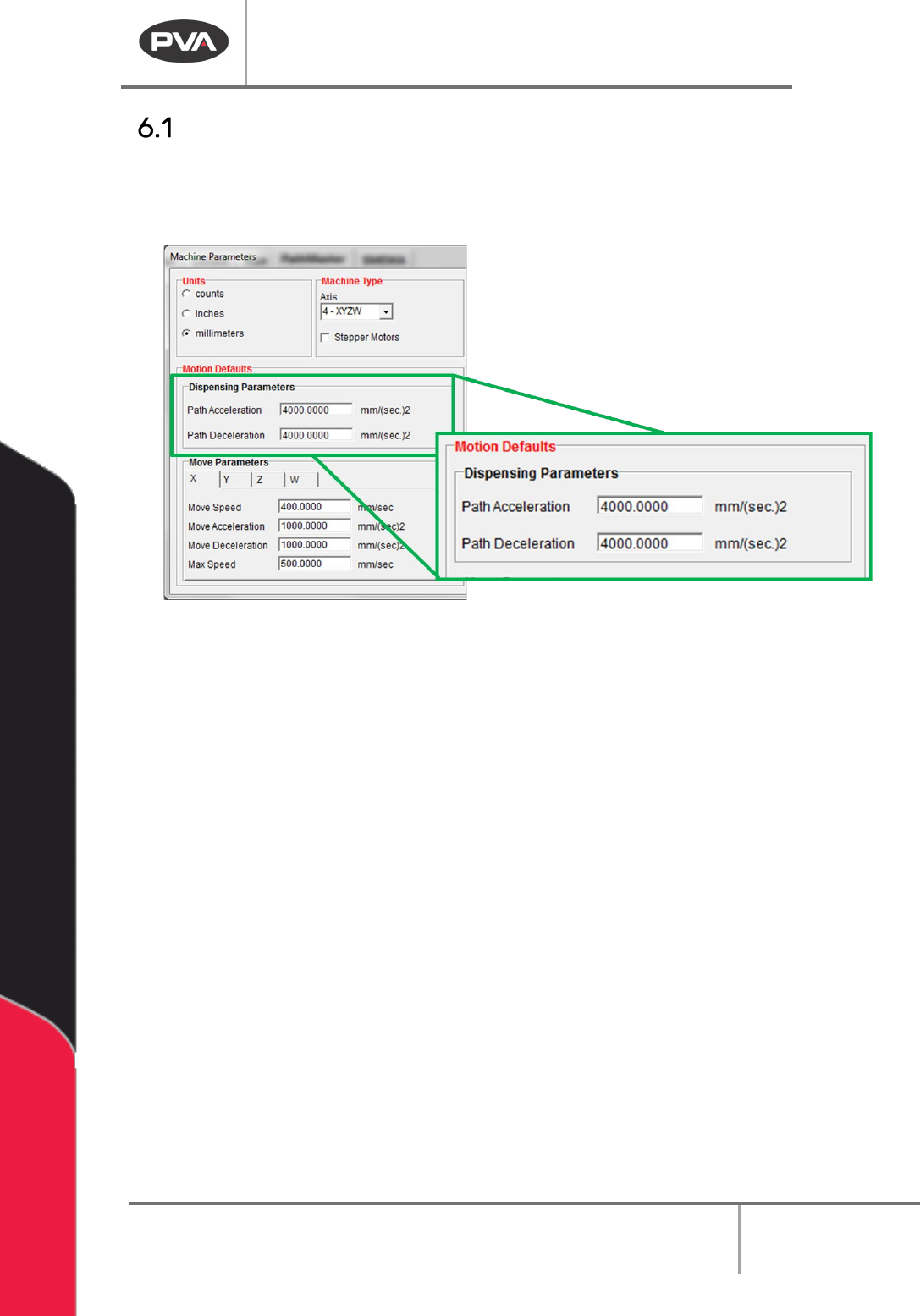
Dispensing Parameters
The dispensing parameters are the default parameters for all coordinated path motion.
These parameters can be modified in each programming function for each path segment.
These settings are found in the Machine Parameters window.
Figure 27: Dispensing Parameters
1. Select
Setup->Machine Parameters
from the Main menu to open the Machine
Parameters window.
2. Set the Path Acceleration and the Path Deceleration speed. This will be the default
acceleration and deceleration for all coordinated motion.
Machine Operation Manual
Revision L /
February 2020
Page 39 of 200
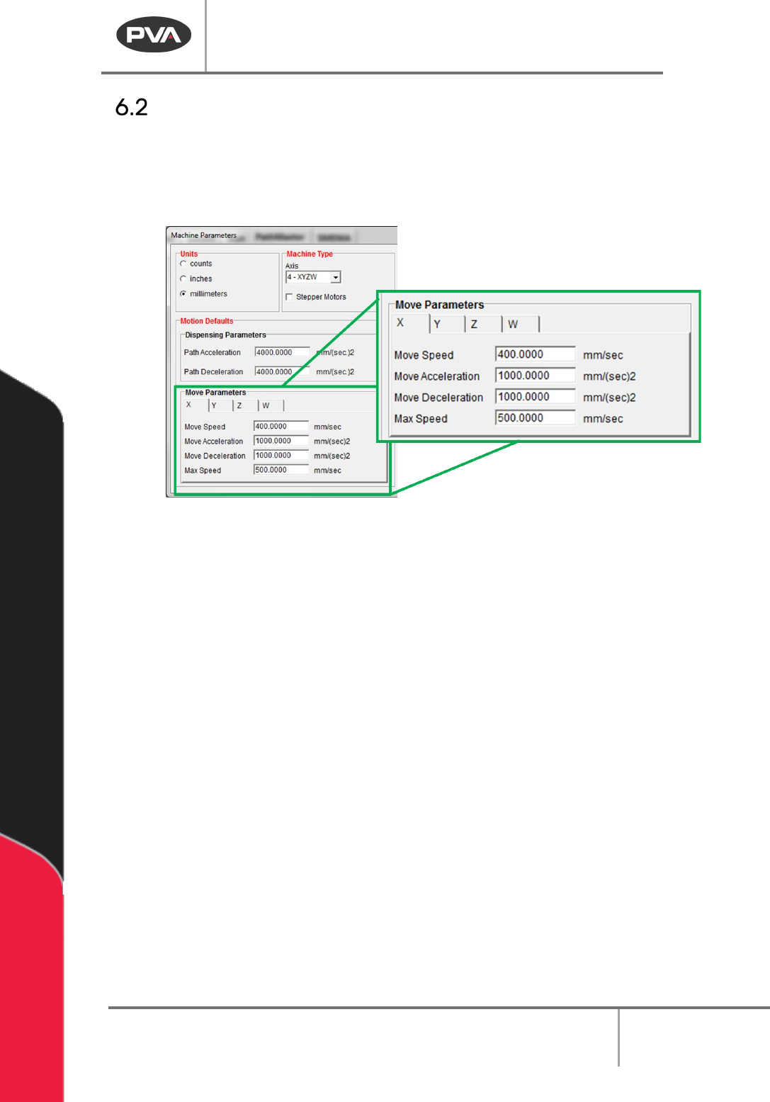
Move Parameters
The move parameters are the default parameters for all independent path motion for each
axis of motion that does not include any dispensing. Select the necessary axis from the
tabs available to view and change the move parameters. These settings are in the Machine
Parameters window.
Figure 28: Move Parameters
1. Select
Setup->Machine Parameters
from the Main menu to open the Machine
Parameters window.
2. Select the necessary Axis Tab (X, Y, Z, W).
3. Set the Move Speed. This is the default speed for all independent path motion.
4. Set the Move Acceleration and Move Deceleration in speed. This is the default
acceleration and deceleration for all independent path motion.
5. Set the Max Speed. This is the greatest speed for an independent path motion.
Machine Operation Manual
Revision L /
February 2020
Page 40 of 200
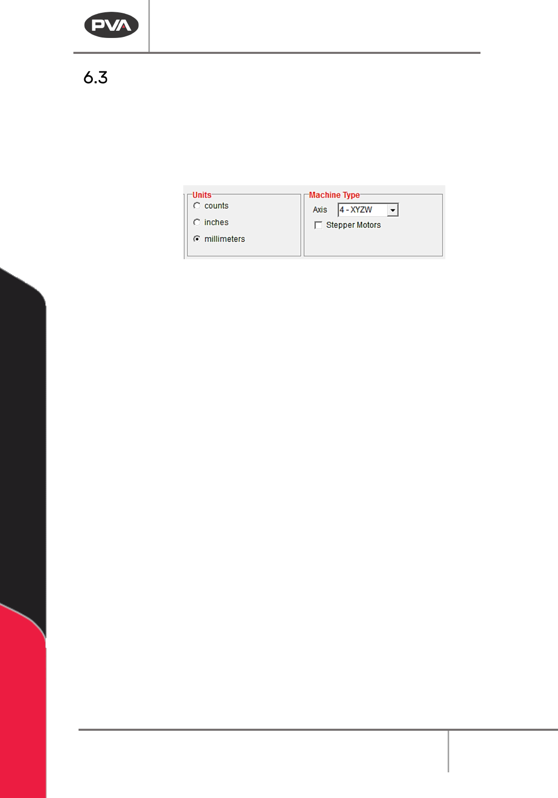
Units and Machine Type
These settings are found in the Machine Parameters window.
1. Select
Setup->Machine Parameters
from the Main menu to open the Machine
Parameters window.
2. Select the necessary measurement system from those shown (counts, inches, or
millimeters).
Figure 29: Units and Machine Type
3. Select the necessary Axis from the drop-down menu to configure PathMaster® for
a two, three, or four axis gantry.
WARNING: If you change axis after a path has been created it may have unintended
consequences. Tool offsets must be updated as necessary. If you remove an axis, the
offset of that Axis will be permanently deleted.
4. Select the Stepper Motors box if your workcell has stepper motors instead of servo
motors. Refer to Figure 29.