PathMaster-REV-L-4.5-1.pdf - 第182页
Machine Operati on Manual Revision L / February 2020 Page 182 of 20 0 Appendix E - Optical Bondi ng with PathMas ter Theory of Operation Optical bond ing with P VA’s Pa thMaste r softwar e should be done with t he bondin…

Machine Operation Manual
Revision L /
February 2020
Page 181 of 200
Spray Valve
Valve stroke and atomizing air are adjustable on spray valves.
The stroke controls the flow of material through the valve. Turn the micrometer knob on
the top of the valve counter-clockwise to increase material flow. Tighten the locking collar
when the flow is satisfactory. Make sure the valve flow rate is correct before you continue.
Atomizing air is controlled by a pressure regulator on the front of the machine. Turn this
clockwise to increase air pressure. This pressure can only be adjusted while the valve is
active. When the flow is satisfactory, push the cap or tighten the locking collar. When first
operating the machine, follow this list of instructions to adjust the spray valve:
1. Set the atomizing air to 0 psi.
2. Take off the spray cap.
3. Turn the stroke down all the way.
4. Purge the valve and open the stroke until the flow is a few drops per second.
5. Put the spray cap on.
6. Purge the valve and adjust the atomizing air until the spray is satisfactory. Test the
spray pattern on scrap.
If the atomizing air pressure is too high, the spray will be misty. If it is too low, there will be
splatter. For thin, solvent based materials 0.5 psi may be all that is necessary, and with
some silicones 15 psi may be necessary.
Programming
Once the satisfactory physical parameters for the delivery system are set, do not change
them. It is better to change the program. Usually, if you increase or decrease the speed of a
dispense path, the material output changes to a satisfactory level.
Program with the dispense valve close to the part surface, but not so close that different
needle length tolerances will cause the needle to touch the product surface.
With the spray valve, start about ¾” (19 mm) above the product surface. With atomizing air,
this should produce a spray width approximately ½” to ¾” (19 mm) wide. If necessary,
adjust the spray height so the pattern on the product is consistent and uniform.

Machine Operation Manual
Revision L /
February 2020
Page 182 of 200
Appendix E- Optical Bonding with PathMaster
Theory of Operation
Optical bonding with PVA’s PathMaster software should be done with the bonding path
template as shown in this document. This document only refers to bonding specific
settings. Please refer to the PathMaster manual for additional information on PathMaster.
PathMaster uses a series of plugins to set values for your specific procedure. Please set all
of the plugin values before you program additional template values.
Path Template
The easiest way to create a bonding sequence is to use the bonding template and change
the values as necessary for your product and process.
• You will need to import the path template from the
'\PathMaster\Samples' folder on
the workcell computer. For additional information on how to import a path, refer to
the PathMaster manual.
Plugins
There are two types of plugins, Setup plugins and Path plugins. Setup plugins are for
machine setup purposes and must be completed before a production path can be run. Path
plugins are program specific. In the case of bonding equipment, setup plugins are used to
measure the positions that are described in the name of the plugins. The wizard plugin
uses the values from the setup plugins to establish the bond base position and the bare
pick head reference measurement height. The descriptions of all setup plugins are in this
document, for information on the path plugins refer to the PathMaster manual.
Machine Operation Manual
Revision L /
February 2020
Page 183 of 200
Setup Plugins
You must set the reference positions before you can create a bond routine. The Setup
Plugins have the four main steps that you must complete to have a succesful routine. The
setup plugins must be done in numerical order (1-4).
Offset values should be taught to the bare datum and pick tool. The part values you set will
calculate the correct distance off of the datum and pick tool.
NOTE: The setup plugins are used to calculate the bonding reference position. Setup
plugins are accessed through the PM machine setup menu and have a global effect.
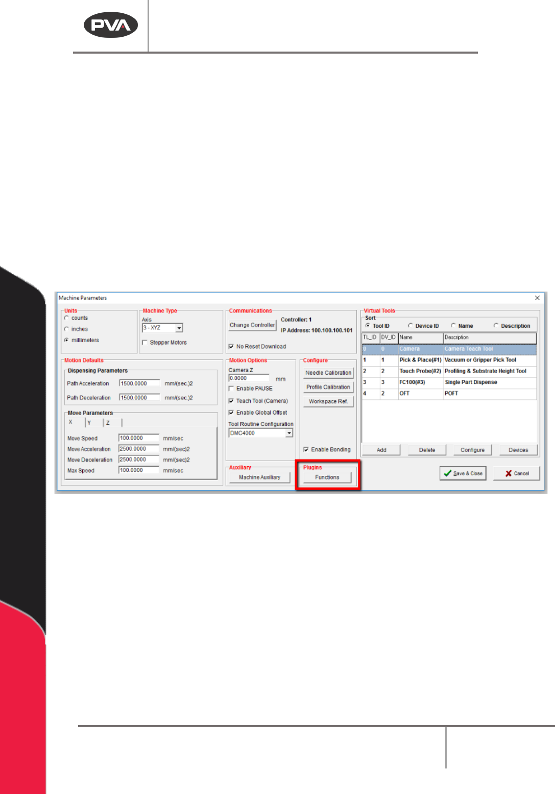
1. Select
Setup->Machine Parameters
from the Main menu to open the Machine
Parameters window.
2. Select the “Functions” button form the Plugins section of the screen.
Figure 195: Plugins, Functions
3. The Setup Plugins screen will open. Use the radial Sort By buttons to sort by
Category.
4. Do the four “Bond Setup” plugins in order.