PathMaster-REV-L-4.5-1.pdf - 第56页
Machine Operati on Manual Revision L / February 2020 Page 56 of 200 Tool Offsets NOTE: Tool O ffsets are only available if the Teach Tool box is checked. Too l offs ets define th e X, Y, theta rel ationship (offset ) bet…
Machine Operation Manual
Revision L /
February 2020
Page 55 of 200
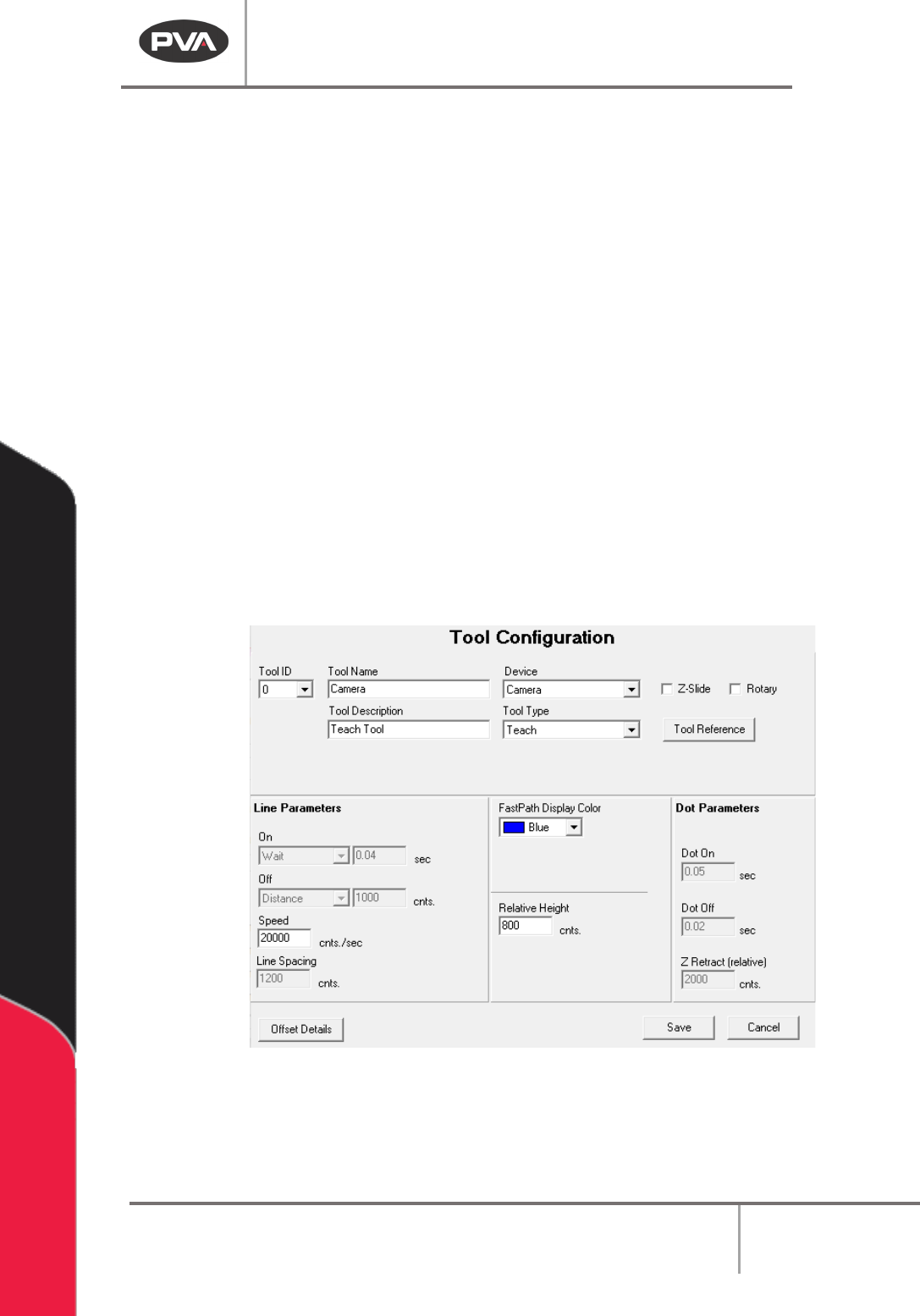
9. Set the tool Off to Wait or Distance and set the time or distance. Wait is the pause
after the path is finished and the tool is off but before the tool goes to the next
point.
Distance is the length of the path traveled after the tool is off but before the
path is done.
10. Set the default Speed for the virtual tool.
11. Set the Line Spacing for the distance between runs when an area path or
rectangular spiral is used.
12. Set the Display Color for the color used for offline programming features.
13. Set the default Relative Height. This is the distance from the surface of the product
to the lowest point of the tool above the product, as taught in the tool offset
function (offline programming only).
14. Set the Dot On Dwell and the Dot Off Dwell time. This will be the default tool on and
tool off time for the Dot function for this virtual tool.
15. Set the Z-Retract (relative) distance. This will be the default relative Z-retract for
the Dot function for this virtual tool.
16. Select “Save” to save your changes and exit. Select “Cancel” to exit and not save
changes.
Figure 50: Teach Tool Configuration
NOTE: Some options in Tool Configuration are changed or disabled when a type of “Teach”
or “Profile” is selected.
Machine Operation Manual
Revision L /
February 2020
Page 56 of 200
Tool Offsets
NOTE: Tool Offsets are only available if the Teach Tool box is checked.
Tool offsets define the X, Y, theta relationship (offset) between the teach tool (usually a
camera) and every other physical tool installed on the workcell. Tool offsets let a teach tool
be used to program paths in PathMaster® and use a different physical tool to playback the
path. PathMaster® must measure the offset for each tool relative to the teach tool for this
to work correctly. In PathMaster®, the tool offsets are defined (setup) with the Tool Offset
option in the Tool Configuration window.
When you teach tool offsets, you must put the tool in the correct state before you teach
the tool position. For example, on a 3-axis system with a dispense valve mounted on a
pneumatic rotary, put the pneumatic rotary in the necessary state (A or B). On a 4-axis
system, put the theta axis in the correct position before you teach the tool offset.
WARNING: If the Teach Tool function is enabled, the Tool Offsets must be set before the
Workspace Reference, Needle Calibration Reference, or Profile Relative Surface positions
are set. Tool Offsets also need to be set before a Tool Change, Needle Calibration, Surface
Height, or a path program is taught.
To Teach Tool Offsets
1. Select
Setup->Machine Parameters
from the Main menu to open the Machine
Parameters window.
2. Select the virtual tool you want to configure the offset for. Double click on the
virtual tool or highlight it and select “
Configure”.
NOTE: Set up the teach tool, tool 0, first. Then set up any additional tools.
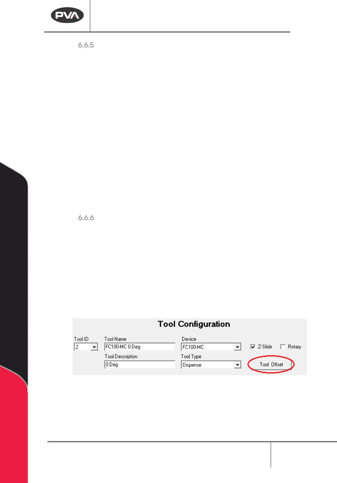
3. Select the “Tool Offset” button in the Tool Configuration window.
NOTE: If you do not have the Teach Tool (Camera) box selected in the Machine Parameters
window you will not see the “Tool Offset” button.
Figure 51: Tool Offset Button
NOTE: Tool 0 (the teach tool) has a “Tool Reference” button, not a “Tool Offset” button, and
the Tool Type is set to ‘Teach’.
Machine Operation Manual
Revision L /
February 2020
Page 57 of 200
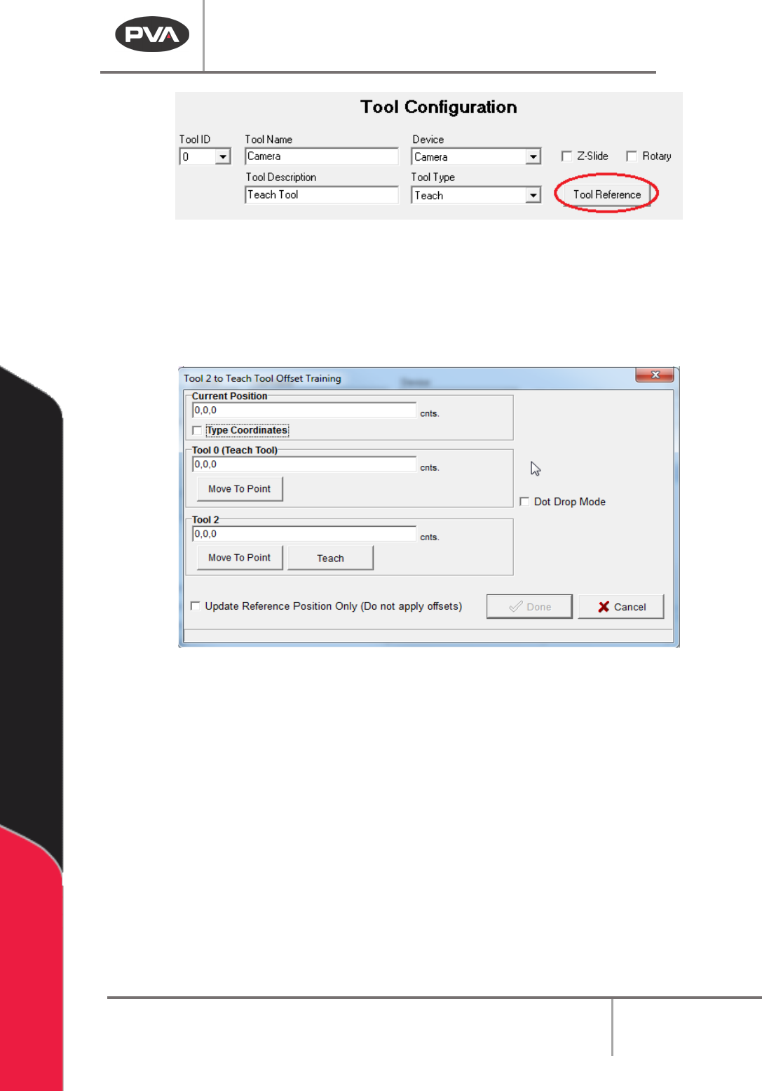
Figure 52: Teach Tool, Tool Reference
4. Move the theta axis (4-axis systems only) to the correct position with the Trackball
or click the “θ” button to move to the last calibrated theta position.
PathMaster® must measure the offset for each tool relative to the teach tool. It is
necessary to teach a tool at a reference or fiducial point.
Figure 53: Run Tool Reference Training Window
5. Move the teach tool above the reference point, which both the teach tool and the
selected tool can reach. Or, select the “
Move to Point” button to move to the teach
tool reference point, if previously taught.
6. When the teach tool is above the reference point, select the “Teach” button. Make
sure Z height and W (optional axis) are correct in the taught position.
7. Move the run tool to the reference point and select the “Teach” button.
8. Select the Update Reference Position Only (Do not apply Offsets) checkbox to
update the reference position only, tool offsets will not be applied. The default is
unchecked, and tool offsets are applied to all corresponding path segments (all
programs, all projects).