PathMaster-REV-L-4.5-1.pdf - 第128页
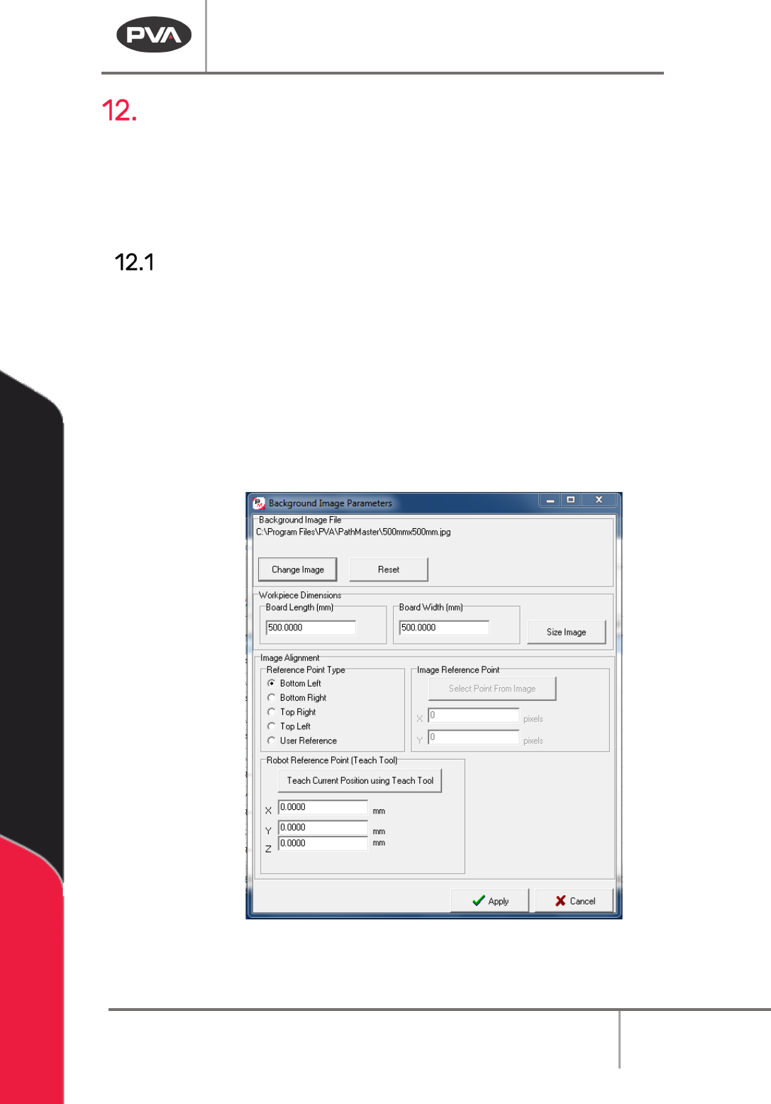
Machine Operati on Manual Revision L / February 2020 Page 128 of 200 Figure 158 : Choose Point s 6. Select “ OK ”. 7. Select the first point o n the image that sh ows in the Choose Ref erence Poin t window. Figure 159 : …
Machine Operation Manual
Revision L /
February 2020
Page 127 of 200
Offline Programming with FastPath
Before you use FastPath™, tool offsets must be configured. Refer to Section 6.6.5 for more
information.
When you are in FastPath your cursor is a crosshair. Each time a point is taught the
crosshair will briefly change to an arrow pointer to show that the point was taught.
Set Up a Background Image
1. Open a new program.
2. Select
Edit->Program->Offline Image
from the main menu.
3. Select “Change Image” to change the background image. If no image is selected, the
default image will be used. The default image is a 500mm by 500mm image with a
workspace of the same size. The background image must be of a known size,
approximately the same size as the area to be dispensed upon.
4. Put the correct values in the Workpiece Dimensions boxes for Board Length and
Board Width.
Figure 157: Background Image
5. Select “Size Image”.
Machine Operation Manual
Revision L /
February 2020
Page 128 of 200
Figure 158: Choose Points
6. Select “OK”.
7. Select the first point on the image that shows in the Choose Reference Point
window.
Figure 159: Select the First Point
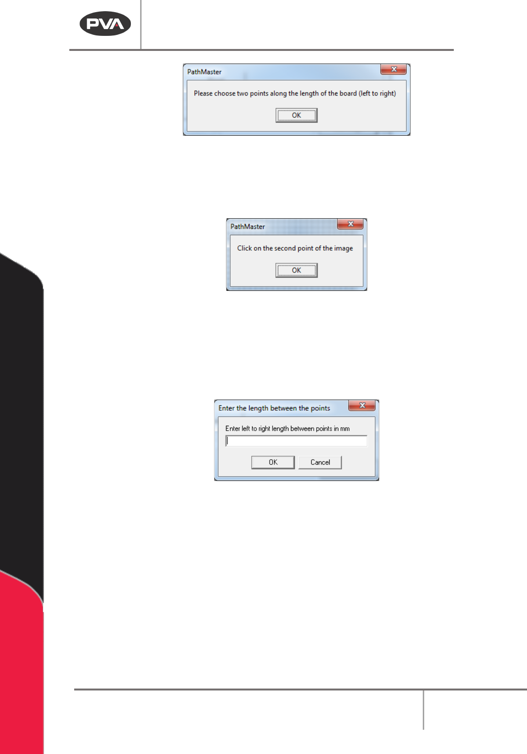
8. Select “OK”.
9. Select the second point.
10. Enter the value of the length between the points in the box.
11. Select “OK”. The Work Piece Dimensions will be updated.
Figure 160: Enter the Length between Points
12. Choose the Reference Point Type.
NOTE: A good reference point is the lower right of your image and the tool 1 coordinates for
the intersection of the front rail and the board stop of your machine.
13. Find the machine coordinates for the same location.
14. Put the tool 1 coordinates in the Robot Reference Point edit boxes.
15. Select “Teach Reference Point”.
16. Select “Apply” to save the changes.
17. Select “Cancel” to exit and not save changes.
Machine Operation Manual
Revision L /
February 2020
Page 129 of 200
Tool Selection
With Tool Selection the tool for path segments in FastPath™ can be selected. Tool selection
is important because tool offsets are applied.
The tool offsets must be setup before FastPath™ is used, for the path program to run
correctly. Select the necessary tool before you select a programming tool. You can change
the tool, but it must be selected before the path segment is completed.
For example: If the first two coordinates of an area are taught with tool 2 and tool 3 is
selected to complete the third point, the path segment will use tool 3.
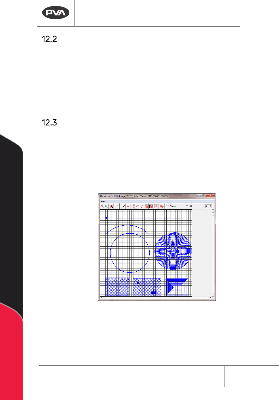
Drawing a Program
1. Select the FastPath™ icon on the programming toolbar to open the FastPath™
window.
2. Use the “Zoom-In” and “Zoom-Out” buttons to adjust the image size.
3. Select a tool to make a path segment.
4. Teach the necessary functions for the tool selected.
5. Close the FastPath™ window and to return to the PathMaster® window.
Figure 161: FastPath
Most PathMaster® programming functions are available when in FastPath™. Programming
functions are used in FastPath™ similar to the way they are used for regular programming.
The FastPath™ points are taught on the board image in the FastPath™ window with the
corresponding tool selected, instead of with the teach pendent.
6. To modify or edit an object, double click on the function.