PathMaster-REV-L-4.5-1.pdf - 第67页
Machine Operati on Manual Revision L / February 2020 Page 67 of 20 0 Playback Paths can b e played with PathMa ster ® or do wnl oaded and run on the work cell. To run an indiv idual path 1. Highlight an indiv idual path …
Machine Operation Manual
Revision L /
February 2020
Page 66 of 200
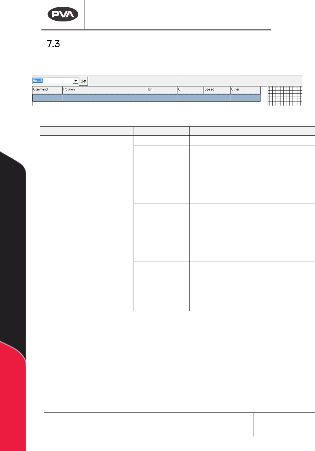
How to Read a Program
The PathMaster® program display is arranged in a table format. Use the chart below to
determine the purpose of the text that appears in each field.
Figure 65: Program Table
COLUMN
USE
EXAMPLE
EXPLANATION
Command
Programmed
Command
DOT
Dot Program
LINE(3D) 3D Line
Position
Coordinates
4555,3000,760
Cartesian coordinates for current point
On Tool or I/O on (1)W.5 Activate tool 1, tool on time of .5
seconds
(2)D300
Activate tool 2, tool on distance of 300
counts
I49 Wait for input 49 to be on
O32
Turn on output 32
Off Tool or I/O off W.75 Deactivate the path’s tool 1, tool off
time of .75 seconds
D500
Deactivate the path’s tool, tool off
distance of 500 counts
I51 Wait for input 51 to be off
O35
Turn off output 35
Speed Path speed 2000 Path speed of 2000 counts per second
Other
Varies according
to path
Z=250
Z-axis relative move of 250 counts
after completing a dot path
NOTE: A command uses all the lines below it until another command reference appears in
the Command column.
Machine Operation Manual
Revision L /
February 2020
Page 67 of 200
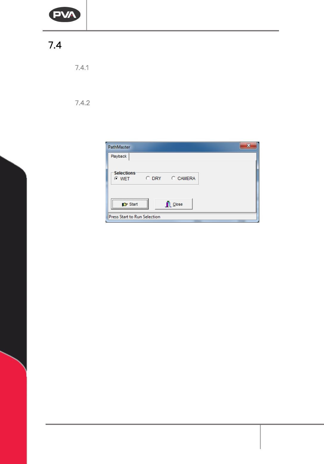
Playback
Paths can be played with PathMaster® or downloaded and run on the workcell.
To run an individual path
1. Highlight an individual path from the PathMaster® window.
2. Select
Run ->Selection
from the drop-down menu or the right-click menu.
To run an entire program
3. Select
Run ->Program
from the drop-down menu or the right-click menu.
4. Before the path runs, the user must select “Wet”, “Dry” or “Virtual Tool 0”. The name
for the third option will be the name of Virtual Tool 0.
Figure 66: Playback
“Wet” playback activates the tool(s) and material will dispense. “Dry” playback does not
activate the tool(s). “
Virtual Tool 0” (replaced by the name of “Virtual Tool 0”) will run the
path with the teach tool at “
Virtual Tool 0” Z, as defined in Machine Parameters instead of
the run tool.
5. Select “Start” to run the path as selected or “Close” to exit without running the
path.
Machine Operation Manual
Revision L /
February 2020
Page 68 of 200
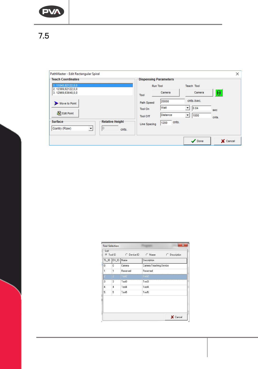
Edit Windows
The operator can change a path segment after it has been created. Double click on the
path segment to show the edit window. The Coordinates box is shown in the upper left-
hand corner of the edit window. All the programmed coordinates are shown.
Figure 67: Example Edit Window
Use the options shown as necessary to edit the paths. Not all options will be shown in
every edit window.
1. Select Move to Point to move to the point highlighted in the coordinates box.
2. Select Edit Point to open the point highlighted in the Coordinates box in the edit
window.
3. Set the Tool Height to “Use the Current Z Height” or “Use Calibrated Z Height,” or, if
the function has surfaces, select the
Surface from the drop-down menu. If
necessary, set the
Relative Height in millimeters.
4. Select the Run Tool.
5. Select (double click) on the necessary tool.
Figure 68: Tool Selection