PathMaster-REV-L-4.5-1.pdf - 第23页
Machine Operati on Manual Revision L / February 2020 Page 23 of 2 00 P rogramming Functions The program ming tool bar show s the most fre qu ently used p rogra mming fu ncti ons. Functio ns that are g reen or o utlined i…
Machine Operation Manual
Revision L /
February 2020
Page 22 of 200
Overview
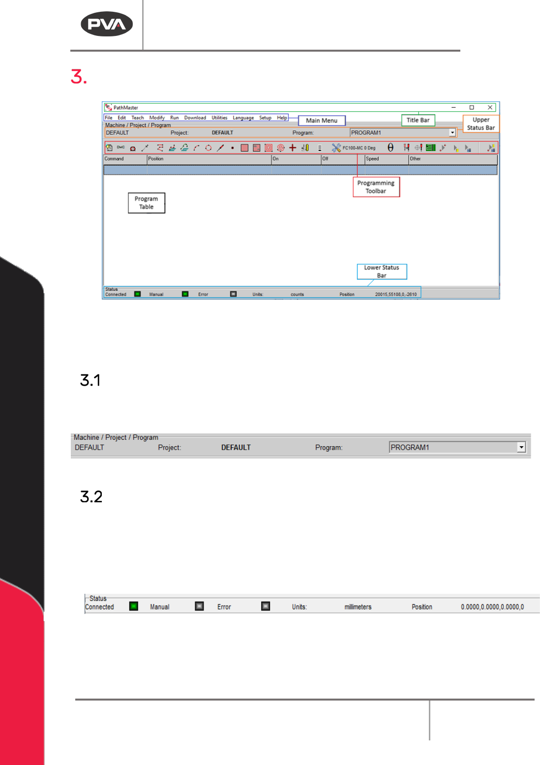
Figure 5: PathMaster® Window
If PathMaster® is opened while Portal is in use, the PathMaster® window will open as an
attached split screen below the Portal window, which will hide the Title Bar.
Upper Status Bar
The upper status bar displays the active machine configuration, current project file and
current path program, which can be changed with the Program drop-down menu.
Figure 6: Upper Status Bar
Lower Status Bar
The lower status bar shows the current status of the workcell. The communication status
between the PC and the workcell is shown in the “Connected” display. The “Manual” display
shows if the workcell is in Manual mode. The “Error” display shows if the workcell is in a
state of error. The Units field gives the measurement system used when programming
paths, and can be changed in the Setup section of PathMaster®.
Figure 7: Lower Status Bar
NOTE: In order to teach path programs online, PathMaster® must be connected to a
workcell that is in Manual mode, and not in a state of error.
Machine Operation Manual
Revision L /
February 2020
Page 23 of 200
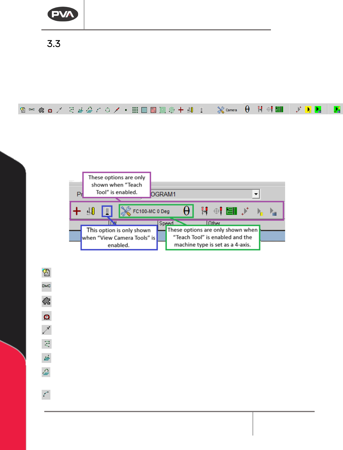
Programming Functions
The programming toolbar shows the most frequently used programming functions.
Functions that are green or outlined in green have the ability to reference surfaces.
Functions that are red do not. With the exception of Polyline, Functions can only reference
one surface. The toolbar you see depends on the workcell controller. The toolbar shown is
for a DMC4000 or newer controller.
Figure 8: Programming Toolbar
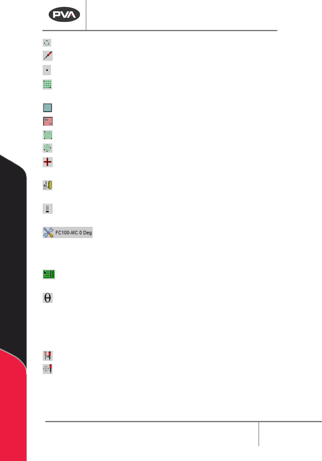
Programming functions are used to create path segments, which make up a path program.
PathMaster® contains a variety of useful programming functions which can be used to
create 2 dimensional and 3 dimensional paths. The most common functions are on the
toolbar, other functions can be accessed from the Teach menu.
Figure 9: Explanation of Functions
Comment – Add comments into the program.
DMC – Teach a DMC command line in the program.
Plugin Select – Select a plugin from a preset list of options.
Dwell – Teach a delay in the program for a set period of time.
Move – Teach a move to a specific location.
2D Path – Teach a 2D path segment and program tool operation.
3D Path – Teach a 3D path segment and program tool operation.
Polyline – Teach 2D or 3D path segments and program tool operations that can make
use of Height Profiling, if applicable.
Arc – Teach an arc path segment and program tool operation.
Machine Operation Manual
Revision L /
February 2020
Page 24 of 200
Circle – Teach a circular path segment and program tool operation.
Tool – Add a tool function (up/down, rotary, etc.).
Dot – Dispense at a defined point for a length of time and program tool operation.
Dot Array – Define a series of dots based on two adjacent points along with X and Y
pitch.
Area – Teach a path segment that covers a rectangular area.
FastMask – Teach a FastMask™ path segment (specify keep out areas).
Rectangular Spiral – Teach a rectangular spiral segment to cover an area.
Circular Spiral – Teach a circular spiral segment to cover an area.
Fiducial – Teach a fiducial A or B command in the path program. The Teach Tool
(Camera) box must be selected in
Setup->Machine Parameters
to see this function.
Surface Height – Teach a surface height command in the path program. The surface
height reading is used to calculate the Profile Z Height for Run tools used during Polylines.
Camera Height – Moves the Z axis to the set camera height from the Machine
Parameters. In the Utilities menu, select “View Camera Tools” to see this function.
Tool State Selector –Open the Tool State Selector menu to select an
option. This will move the selected tool to the correct programmed position. This is only
shown if the Teach Tool box is selected under the Tools section in the Machine Parameters
Window and PathMaster® is setup for a 4-axis machine.
FastPath – Open the FastPath™ window for offline programming. The Teach Tool
(Camera) box must be selected in
Setup->Machine Parameters
to see this function.
Theta- Move the selected tool to the calibrated W-axis position (theta). The Theta
button in all command forms and in the Main Grid now shows an indicator color
• Yellow means the Theta axis is not at the proper coordinate for the selected Teach
Tool
• Green means the Theta axis is at the proper coordinate +- the value in the
ThetaDeadband string of Pathmaster.ini
Tool Change- Correct the position of a tool and apply offsets.
Tool Calibration –Used to change tool offsets and set the profile calibration.