PathMaster-REV-L-4.5-1.pdf - 第84页
Machine Operati on Manual Revision L / February 2020 Page 84 of 2 00 PolyLine (DMC 4000) A Polyline is a pat h made of l ines and arcs. Poly line s are used whe n it is nec essary to change dire ction qu ickly , at high …
Machine Operation Manual
Revision L /
February 2020
Page 83 of 200
3D Path
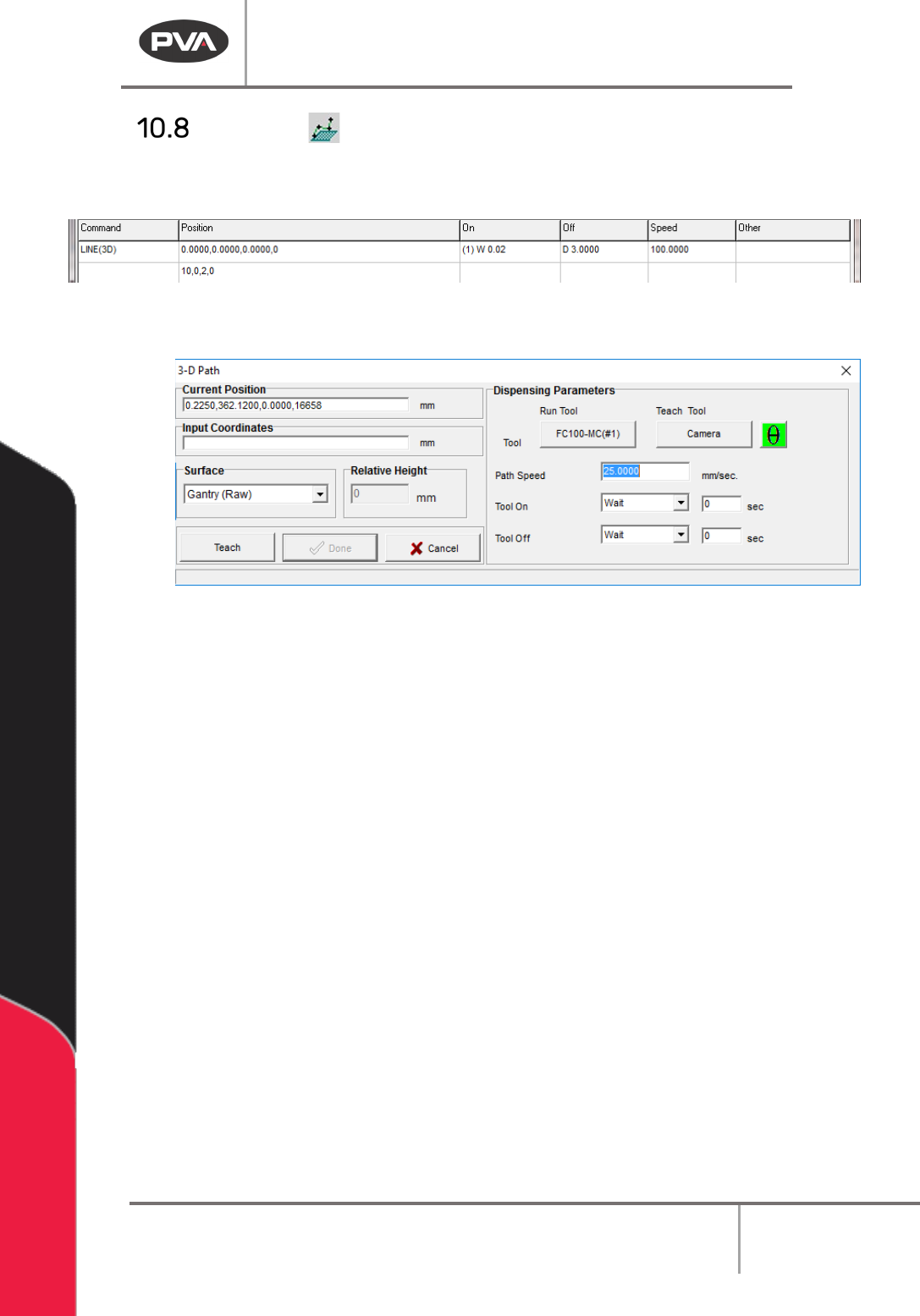
This function teaches 3D path segments. Refer to Section 10.1 for definitions of the tool
functions.
Figure 90: Programmed 3D Line Command
1. Select the 3D Path function.
Figure 91: Teach 3D Line
2. Select the Run Tool. Select (double click) the necessary tool from the Tool Selection
window. Refer to
Figure 68.
3. Select the Teach Tool if necessary. Select (double click) the necessary tool from the
Tool Selection window. Refer to
Figure 68.
4. Select “θ” to move the selected tool to the calibrated W-axis position (theta).
NOTE: The “θ” button will only be available on 4-axis machines. When you use the “Teach
Tool” (virtual tool 0) it is not necessary to select this button.
5. Select the Surface from the drop-down menu. In some units, you can set the
Relative Height.
6. Set the Path Speed.
7. Set the Tool On to “Wait” or Distance” and set the time or distance in the box.
8. Set the Tool Off to “Wait” or “Distance” and set the time or distance in the box.
9. Select the “Teach” button or use the Teach pendant to input the commands in the
Input Coordinates box.
10. Select “Done” to save the changes, or “Cancel” to exit and not save changes.
11. To edit a 3-D Path, double click on the path and change the command in the edit
window. Refer to Section 7.5.
Machine Operation Manual
Revision L /
February 2020
Page 84 of 200
PolyLine (DMC 4000)
A Polyline is a path made of lines and arcs. Polylines are used when it is necessary to
change direction quickly, at high speeds, during a dispense. Polyline, in Pathmaster® 4.3,
uses surface height readings (taught before a polyline is used). Surface Height readings
and the Calibrated Z Height of a tool (Section
Error! Reference source not found.), account
for differences in individual part height and paths are adjusted to dispense correctly.
New Polyline
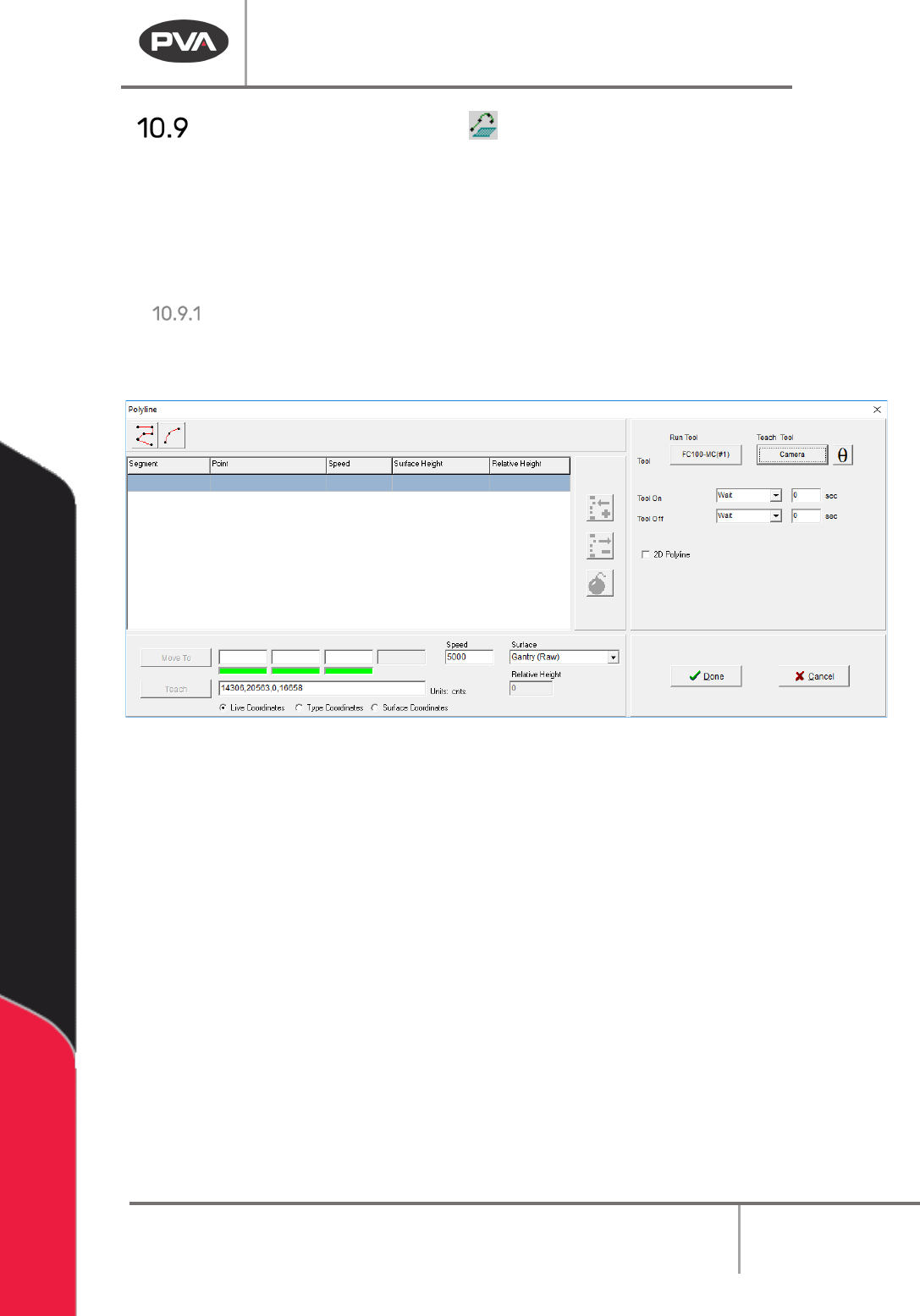
1. Click on the Polyline or select Teach > Polyline > Create New from the Main Menu to
open the Polyline Teach Interface.
Figure 92:PolyLine Teach Window
2. The Bomb button ‘explodes the polyline’. All the taught segments and arcs move
into the main path program as separate segments. When a line is exploded, the
height profiling feature cannot be used.
3. When 2D Polyline is enabled, a single Z height is taught for all the polyline segments.
Select the “
2D Polyline” checkbox to use this option.
4. Select either a Polyline or Arc from the top of the Polyline teach window. Follow the
prompts to teach the points.
Machine Operation Manual
Revision L /
February 2020
Page 85 of 200
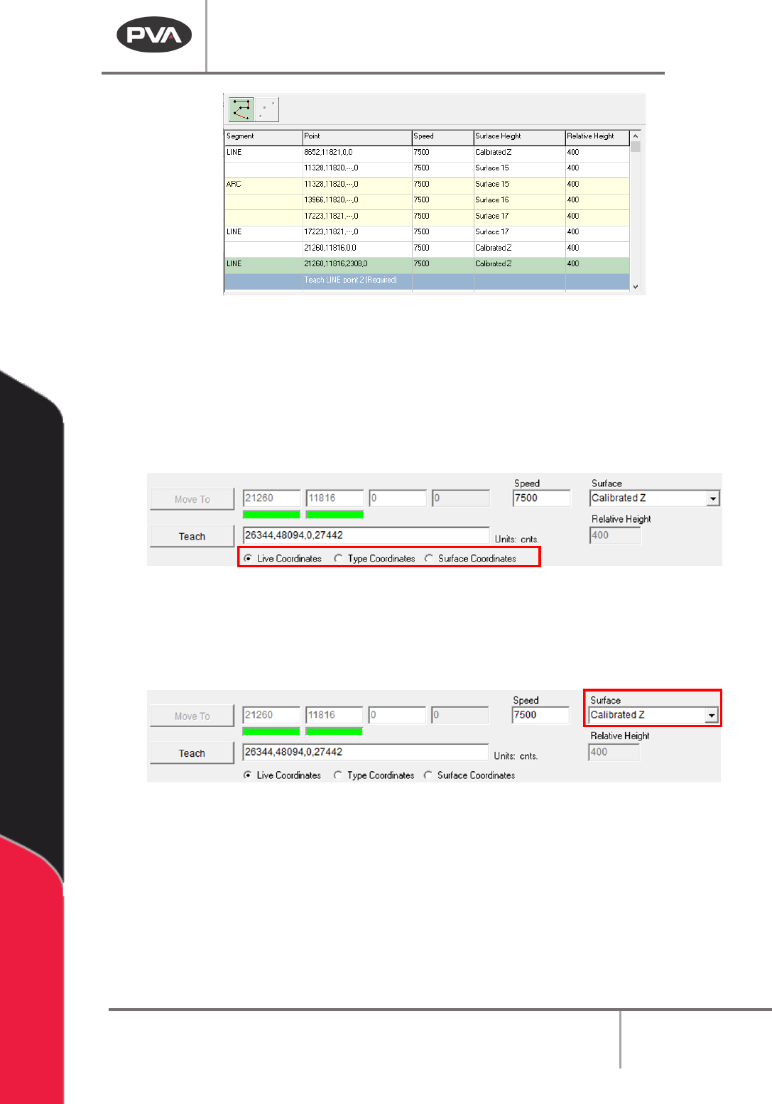
Figure 93: Polyline Line Segment Teaching
5. Use the Coordinate Selection radio buttons and Surface dropdown selection to Z
coordinate options. The radio buttons select between:
Live Coordinates: The end effector’s current gantry position.
Type Coordinates: User types in the coordinates with the keyboard.
Surface Coordinates: Where the Surface Height commands, that are valid for this
polyline, were taught.
Figure 94: Teach Radio Buttons
NOTE: Only surfaces that are in the program grid and are in the path program before the
point of insertion of the polyline will be in the dropdown.
6. Use the Surface drop-down menu to set the Z-plane for a selected Polyline point.
Figure 95: Teach Surface Dropdown
• Gantry (Raw) uses the Z coordinate exactly as it was taught.
• Gantry (Relative) uses the Z coordinate that was taught, and subtracts the “Relative
Height” numeric field’s current value.
• Calibrated Z uses the Run Tool Reference Z for the current run tool, and subtracts
the global “
Relative Height” set for that tool in Tool Configuration.